Bi-directional differential pressure flow sensor

a flow sensor and differential pressure technology, applied in the direction of instruments, pressure difference measurement between multiple valves, liquid/fluent solid measurement, etc., can solve the problems of reducing the sensitivity and responsiveness of flow measurement, erroneous readings, and relatively high installation costs of systems

Inactive Publication Date: 2004-04-27
ROSEMOUNT INC
View PDF149 Cites 72 Cited by
  • Summary
  • Abstract
  • Description
  • Claims
  • Application Information

AI Technical Summary

Problems solved by technology

Such systems have relatively high installation costs due to the need to attach an external pressure sensor to the pipe, and to provide leakage protection at the locations where the pipe is tapped.
Additionally, impulse lines attenuate the pressure signals and introduce delays thereby reducing the sensitivity and responsiveness of the flow measurement.
Also, in gas applications, condensing gases in the impulse lines can cause erroneous readings.
Furthermore, the use of impulse lines can also render these types of flow measuring systems sensitive to their position.

Method used


Image

  • Bi-directional differential pressure flow sensor
  • Bi-directional differential pressure flow sensor
  • Bi-directional differential pressure flow sensor

Examples


Embodiment Construction

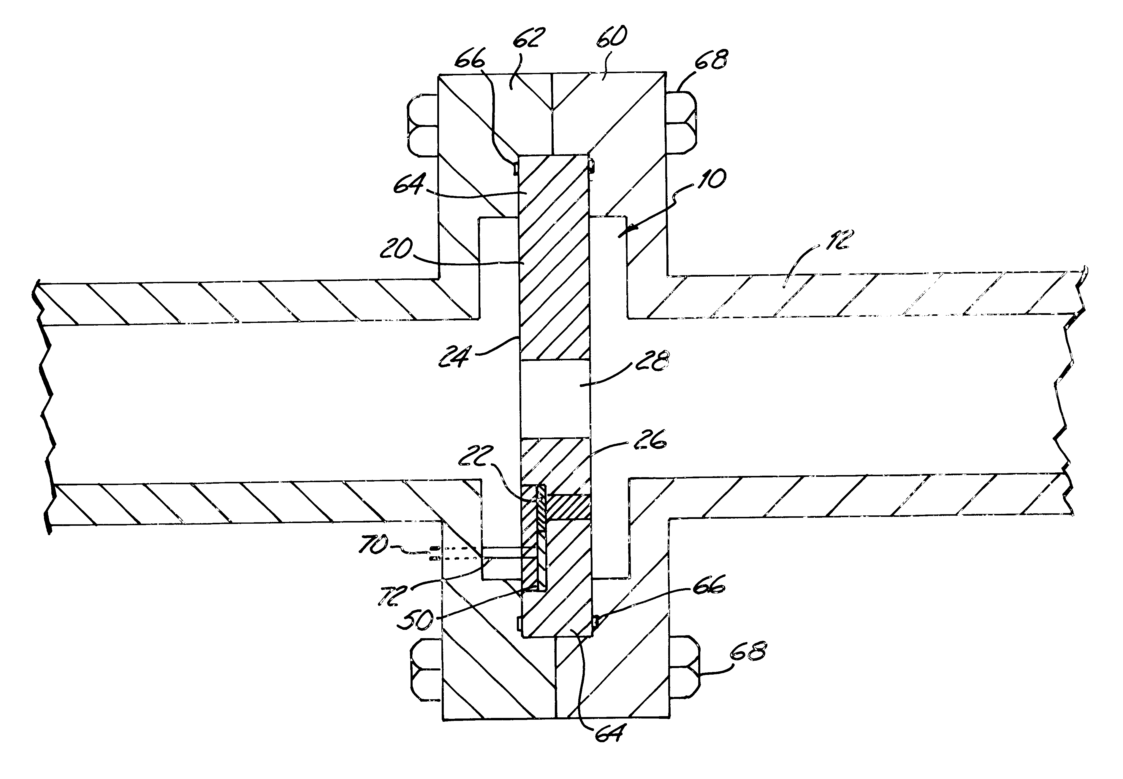
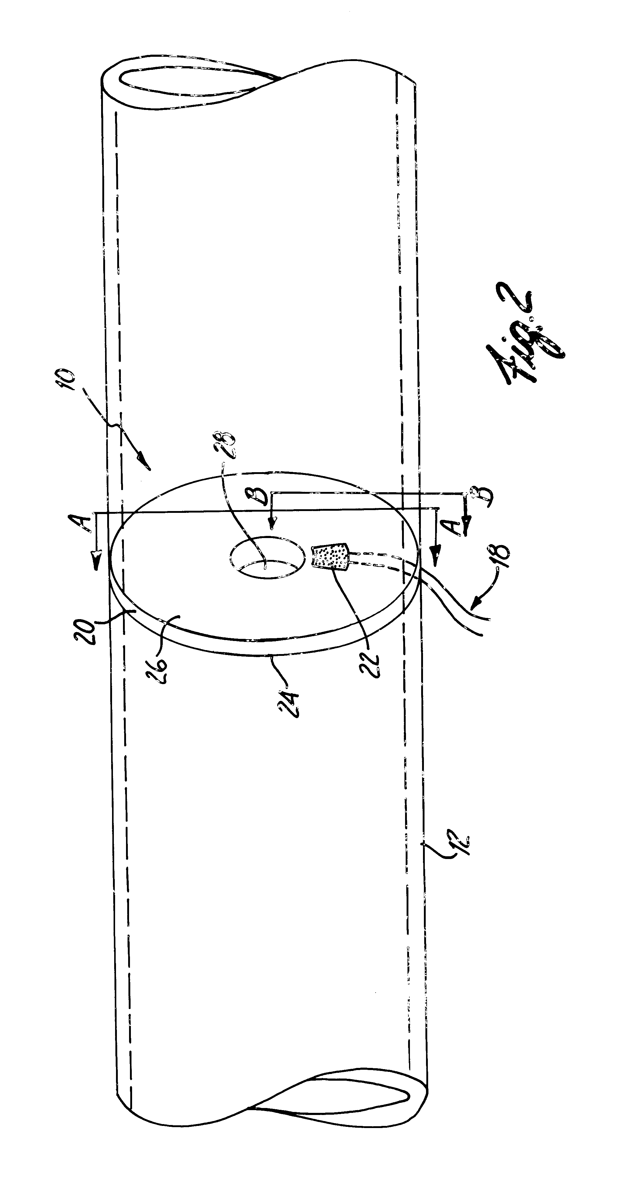
The present invention provides a bi-directional differential pressure flow sensor, in which components of a differential pressure sensor are integral with the flow restriction member. The flow sensor can be placed inline with the fluid flow such that the flow restriction member produces a pressure drop which can be sensed by the differential pressure sensor. The differential pressure sensor is configured to produce a pressure signal that is indicative of the sensed pressure drop. Processing electronics, coupled to the differential pressure sensor, is adapted to produce a flow rate signal that is indicative of the magnitude and direction of a flow rate of the fluid flow as a function of the differential pressure signal.

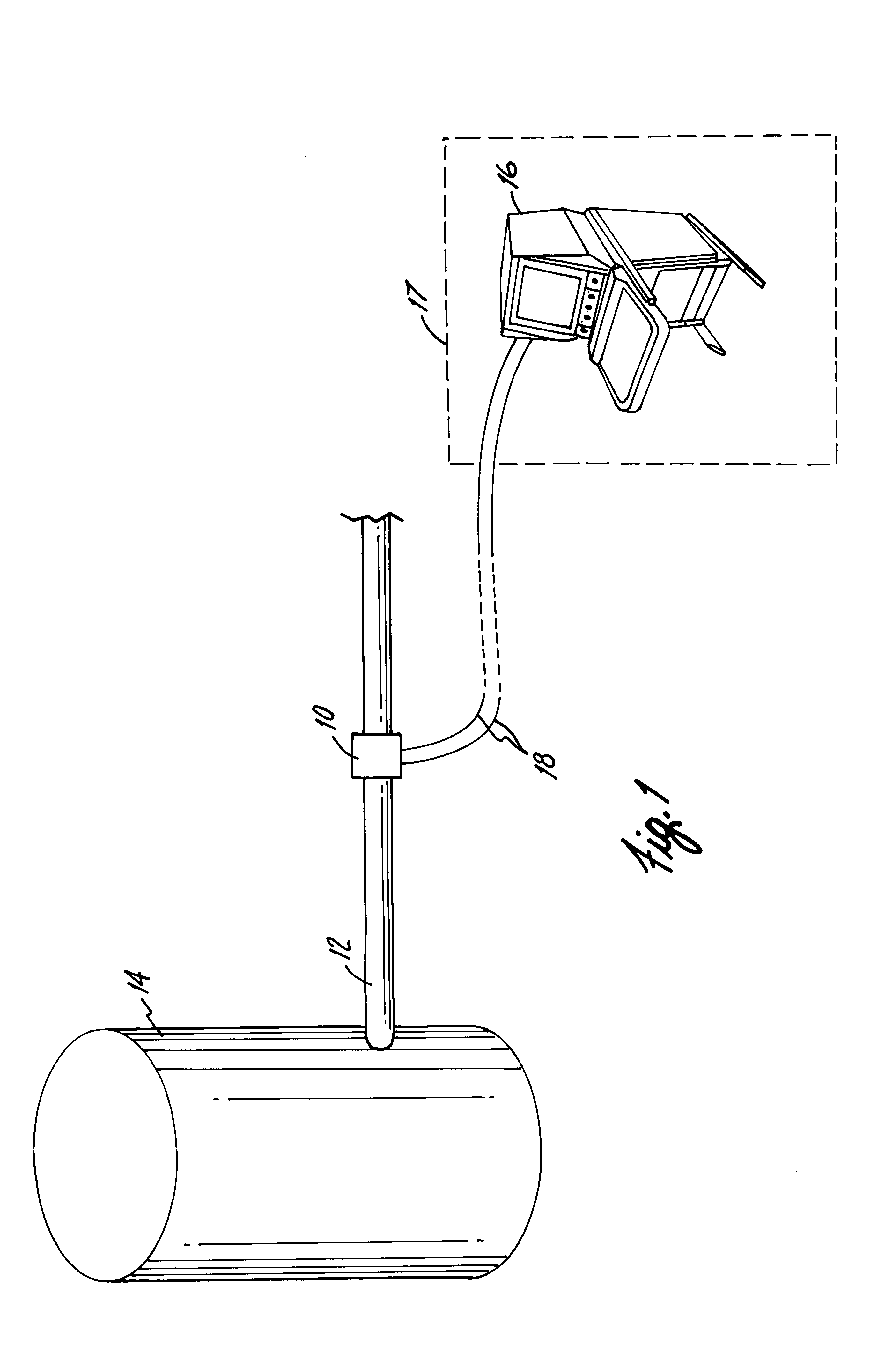
FIG. 1 depicts an example of a processing plant and illustrates an environment in which the flow sensor of the present invention, generally designated as 10, can be used. Flow sensor 10 is installed inline with pipe 12 to produce and sense a pressure drop which can be ...


PUM


Abstract

Disclosed is a bi-directional differential pressure flow sensor that is configured to establish a direction and flow rate of a fluid flow. The flow sensor includes a flow restriction member, a differential pressure sensor, and processing electronics. The flow restriction member is configured to produce a pressure drop when placed inline with the fluid flow. The differential pressure sensor is embedded or integral with the flow restriction member and produces a differential pressure signal that is indicative of the pressure drop. The processing electronics produces a flow rate signal that is indicative of the direction and flow rate of the fluid flow as a function of the differential pressure signal.

Description

BACKGROUND OF THE INVENTIONThe present invention relates to a bi-directional flow sensor used to measure flow rate of a fluid flow. More particularly, the present invention relates to a differential pressure flow sensor of the type using a flow restriction member to produce a pressure drop within the fluid flow, a measurement of which can be used to establish the direction and flow rate of a fluid flow.Fluid flow sensors can be used in many different applications, such as in industrial process control environments, to measure flow rates of process fluids (liquids and gases) and provide flow signals for flow indicators, controls, and flow volume metering. Differential pressure flow sensors measure the fluid flow rate in a pipe or conduit by measuring a pressure drop across a discontinuity within the pipe. One way to form the discontinuity is to place a flow restriction member or primary element within the pipe to produce the desired pressure drop. One such flow restriction member is ...

Claims


Application Information

Patent Timeline
Patent Type & Authority Patents(United States)
IPC IPC(8): F15B15/28F15B15/00G01F1/42G01F1/44G01F1/34G01F1/40G01F1/50G01F1/36G01F1/00G01F15/02
CPCF15B15/2838G01F1/40G01F1/42G01F1/44G01F1/50
Inventor WIKLUND, DAVID E.KROUTH, TERRANCE F.BRODEN, DAVID A.SCHUMACHER, MARK S.
Owner ROSEMOUNT INC
Why Eureka
Try Eureka