
Automatic disc repair system

a disc repair and automatic technology, applied in the field of automatic disc repair systems, can solve the problems of distorting the laser light and inability to accurately read digital information

Inactive Publication Date: 2004-04-27
AVS SUPPLY
View PDF7 Cites 15 Cited by
  • Summary
  • Abstract
  • Description
  • Claims
  • Application Information

AI Technical Summary

Problems solved by technology

If the plastic layer becomes scratched or stained, the laser light will distort and not accurately read the digital information.

Method used


Image

  • Automatic disc repair system
  • Automatic disc repair system
  • Automatic disc repair system

Examples


Embodiment Construction

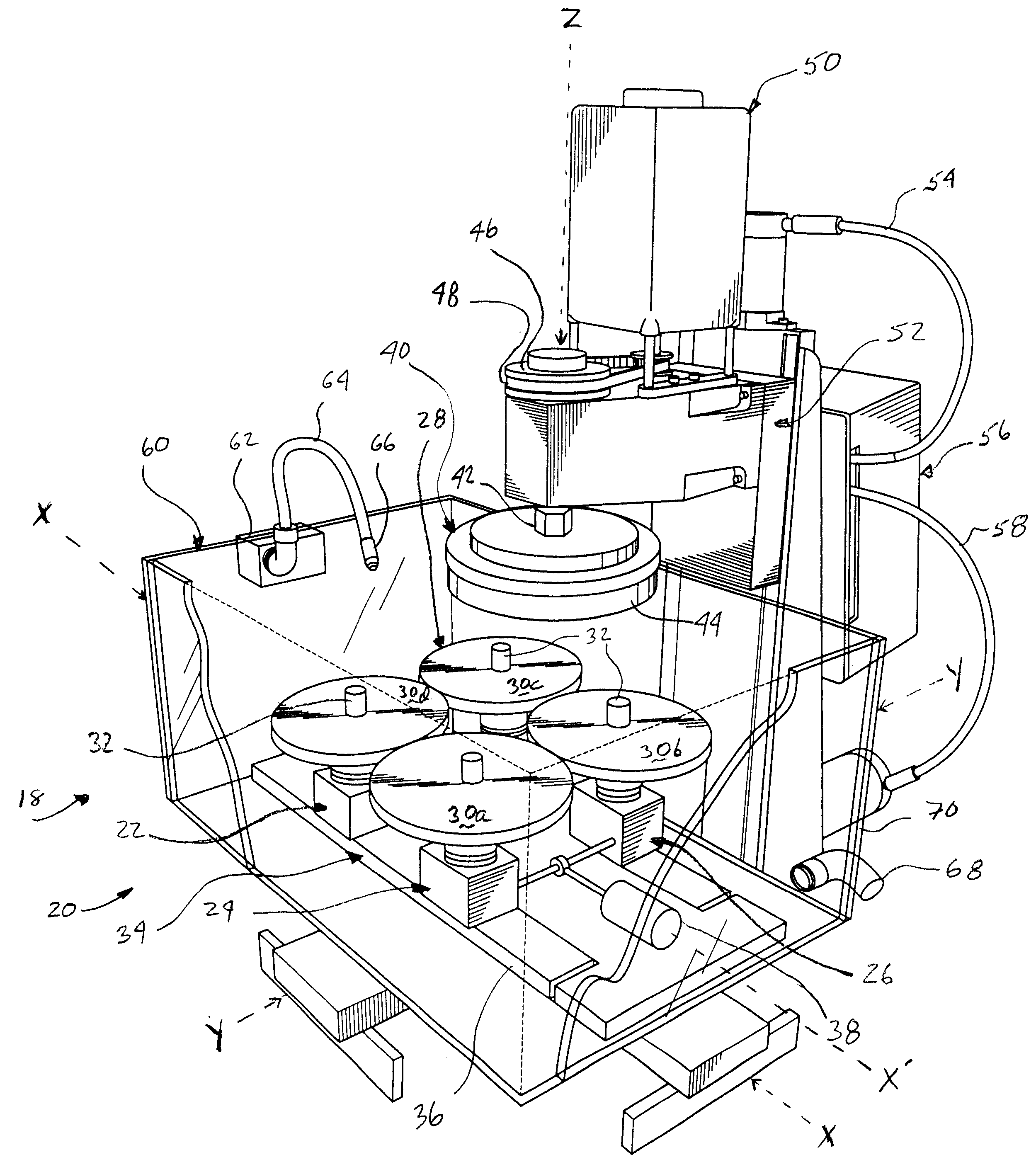
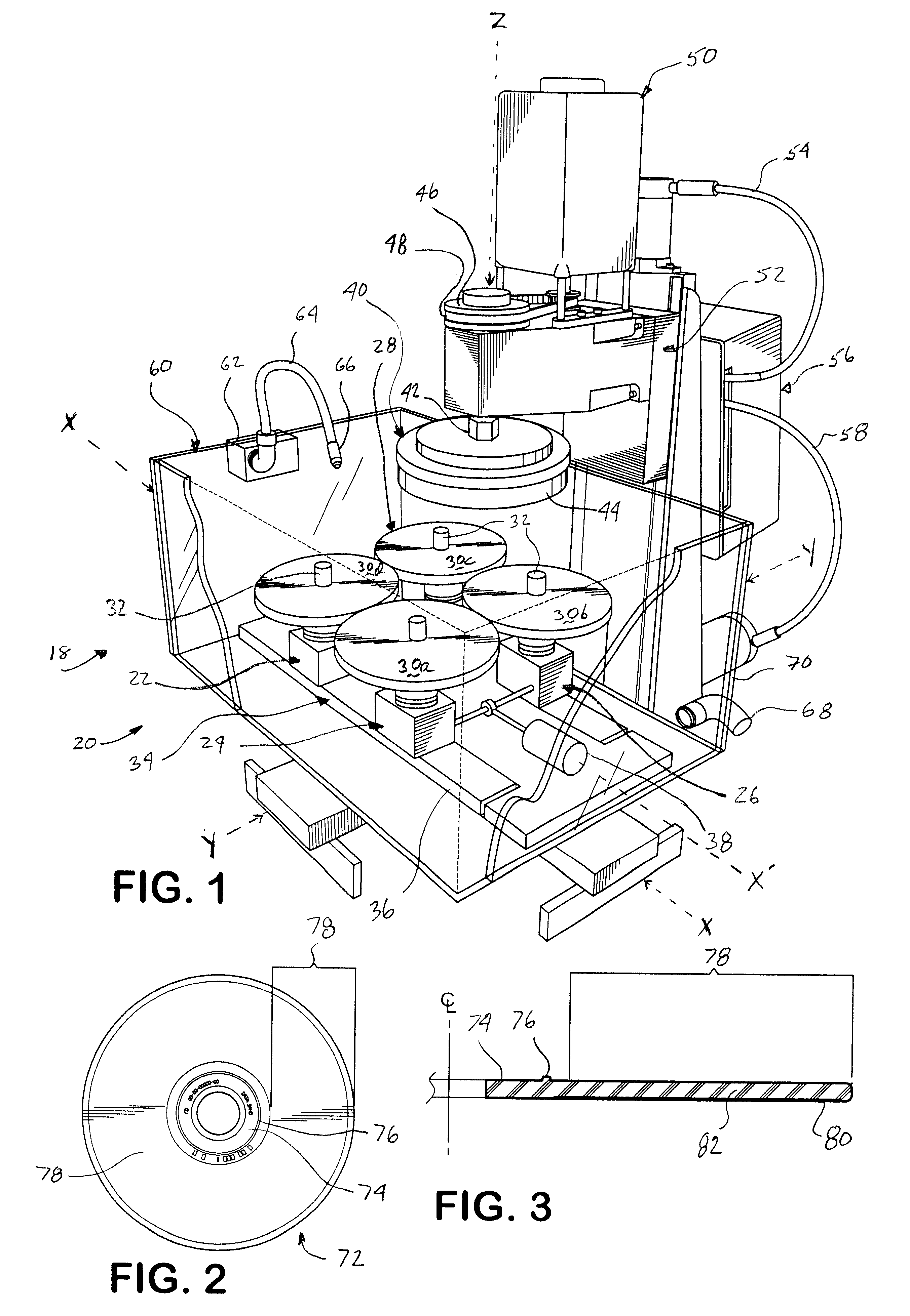
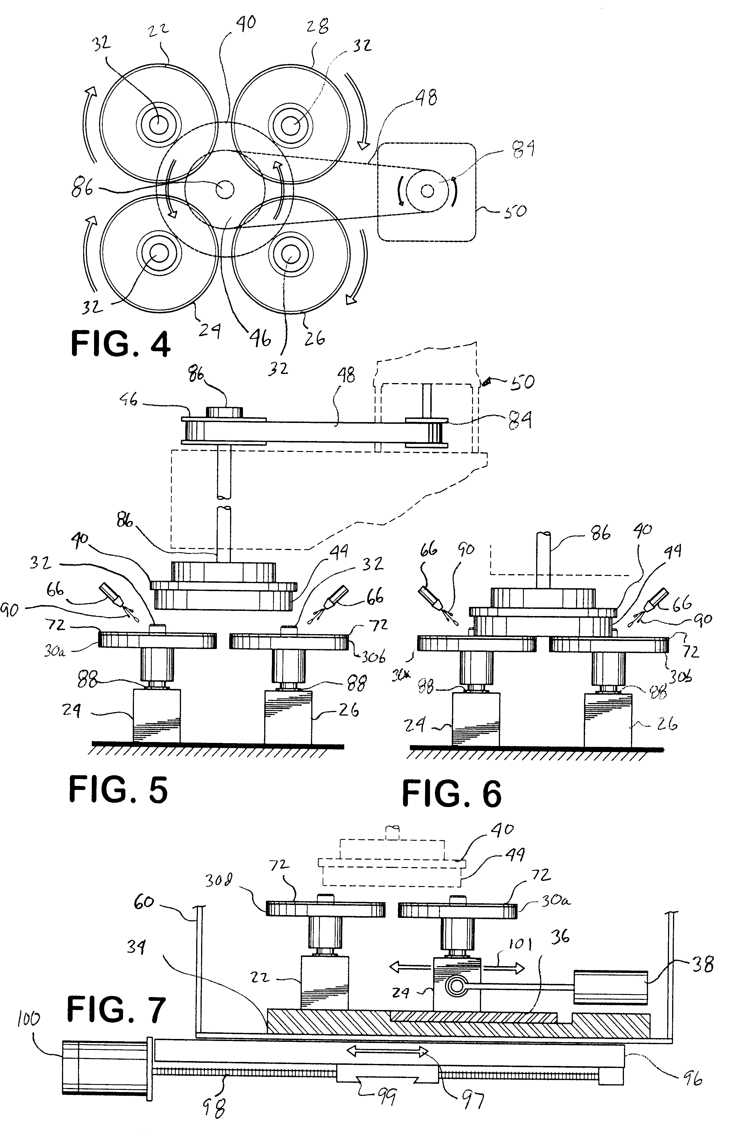
Illustrated in FIG. 1 is a perspective view of the automatic disc repair system 20 (illustrating a single station 18) according to a preferred embodiment of the present invention. In the illustrated embodiment, there are preferably four rotatable disc supports 22, 24, 26, and 28. Preferably, each rotatable disc support 22, 24, 26, and 28 comprises a respective support surface 30a, 30b, 30c, and 30d, and a central spindle 32. Preferably, each respective support surface 30a, 30b, 30c, and 30d is approximately 43 / 4 inches in diameter, however under appropriate circumstances, other sizes may suffice (preferably sized to match the disc being refurbished). Preferably, the spindle 32 is approximately 5 / 8 inches in diameter (to fit the central aperture on a disc).

Preferably, rotatable disc supports 22, 24, 26, and 28 are attached to an adjustable base 34. Preferably, adjustable base 34 may be adjusted along two axis, Axis X and Axis Y. In addition, rotatable disc supports 22 and 28 are pref...


PUM

PropertyMeasurementUnit
sizeaaaaaaaaaa
timeaaaaaaaaaa
grit sizesaaaaaaaaaa

Abstract

An automatic system for repairing scratches on optically-read discs, (e.g., compact discs often called "CD's" or DVD's). More specifically, an automatic system for refurbishing a plurality of disc surfaces at substantially the same time, such that when refurbished, an optical reader, which uses a laser to read digital information stored on such a disc, can read the digital information on the disc without the optical distortion caused by a scratch.

Description

This invention relates to an automatic system for repairing scratches on optically-read discs, e.g., compact discs (often called "CD's" or DVD's). More specifically, this invention provides an automatic system for refurbishing a plurality of disc surfaces at substantially the same time, such that when refurbished, an optical reader, which uses a laser to read digital information stored on such a disc, can read the digital information on the disc without the optical distortion caused by a scratch.Typically, digitally recorded discs, known commonly as "CD" discs or "DVD" discs, contain audio or video information. The digital information is currently interpolated or read by an optical reader that uses one or more laser beams or other light amplified beams to read the digital information. The current state of the art of manufacture of these CD discs is such that they are comprised of a round disc composed of a synthetic material (e.g., plastic), with a typical diameter of approximately ...

Claims


Application Information

Patent Timeline
Patent Type & Authority Patents(United States)
IPC IPC(8): B24B7/22B24B7/20G11B23/50
CPCB24B7/228G11B23/505
Inventor LALLI, EDWARD A.DOHERTY, WILLIAM M.DOHERTY, JR., JOHN L.
Owner AVS SUPPLY
Learn More