
Low noise line powered DAA with differential feedback

a technology of differential feedback and low noise, applied in the direction of current supply arrangement, telephonic communication, electric devices, etc., can solve the problems of extremely constrained power budget, limit the ability of a modem to derive power from the telephone line, and limited maximum current drawn from the telephone lin

Inactive Publication Date: 2004-05-04
LUCENT TECH INC +1
View PDF20 Cites 23 Cited by
  • Summary
  • Abstract
  • Description
  • Claims
  • Application Information

AI Technical Summary

Problems solved by technology

Unfortunately, although operating an acceptable length of time when running typical application programs, the modems and other data communication devices of a portable computer utilize a large amount of power when communicating over a telephone line.
Thus, although portable computer devices operate a sufficient length of time for quick data transfers over a modem powered completely by a battery, they typically require that external AC power be applied to allow for longer uses of the modem.
The DC power inherent in a telephone line provides a convenient source of power, but there are often limitations and restrictions which limit the ability of a modem to derive power from the telephone line.
Thus, the maximum amount of current drawn from the telephone line is limited.
Modems which are designed to be powered entirely from the telephone line are known, but these designs either suffer from an extremely constrained power budget, or are wasteful of the available current.
Moreover, modems in general are also subject to government constraints, e.g., FCC Part 68 requirements for telephones in the U.S., and limitations on effects and noise which may be placed back on the telephone line, placing further restrictions on the use of power from the telephone line.
This unfortunately requires products incorporating the DMs to be manufactured and packaged separately for each of a plurality of varying countries.

Method used


Image

  • Low noise line powered DAA with differential feedback
  • Low noise line powered DAA with differential feedback
  • Low noise line powered DAA with differential feedback

Examples


Embodiment Construction

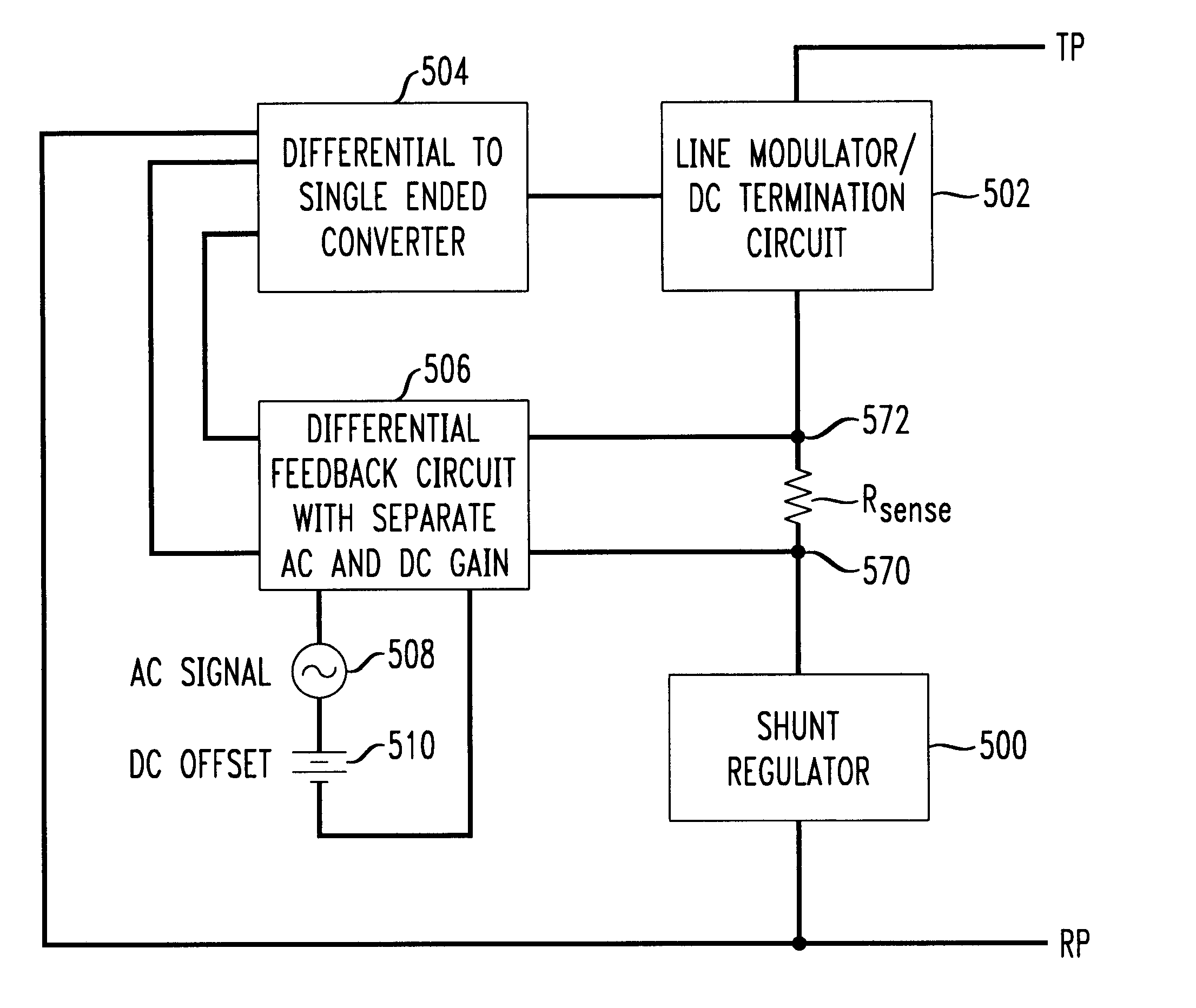
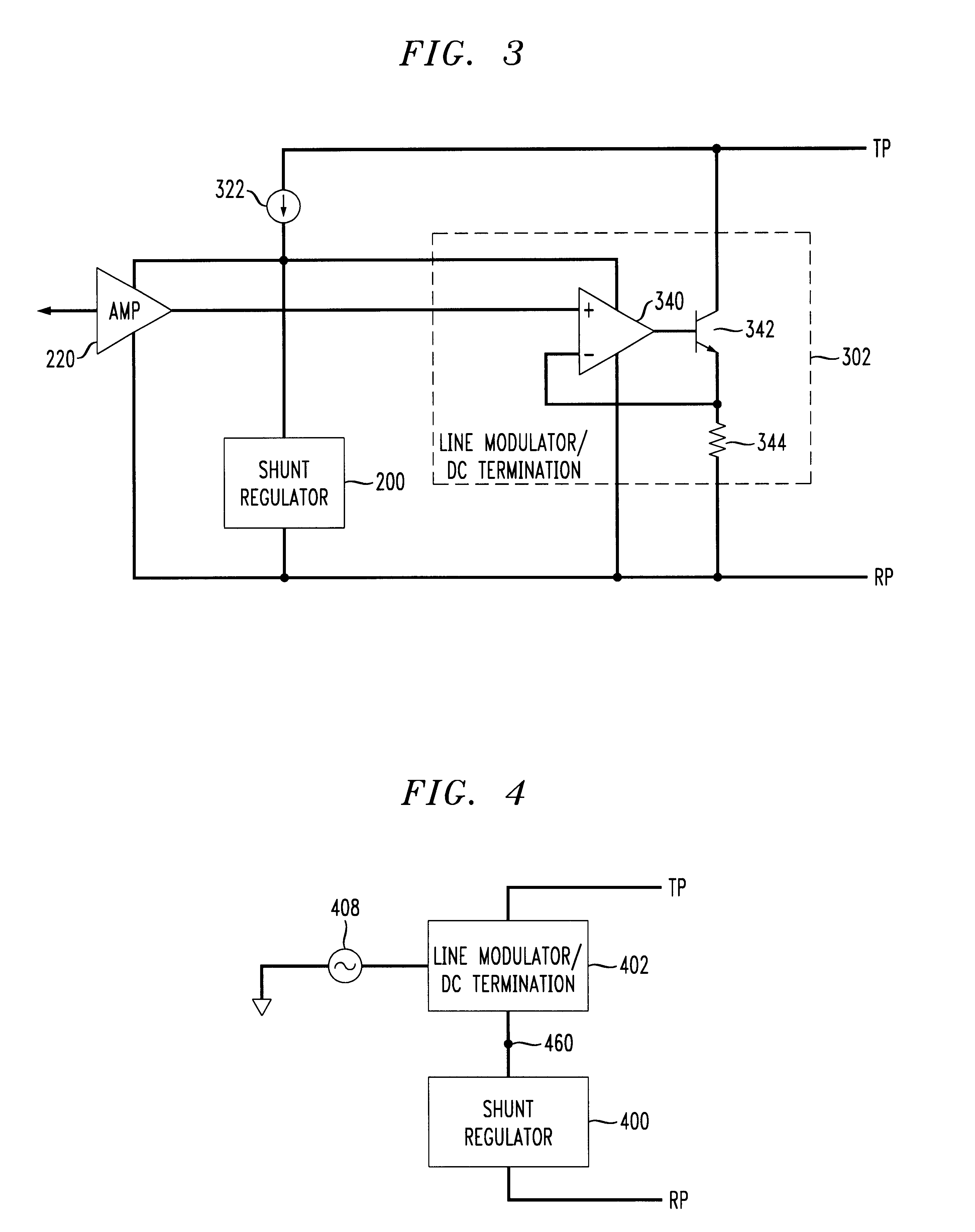
A driving motivation of the present invention was to provide a line powered DM device having reduced noise which is otherwise present. The present invention is particularly useful for use with modems or other line powered data sources, including a digital signal processor (DSP) which provides a modulating AC signal for driving a line modulator. Although a DSP is not required to practice the present invention, the use of a line powered DSP generally increases the noise of a DAA and thus makes the need for reduced noise techniques that much more acute.

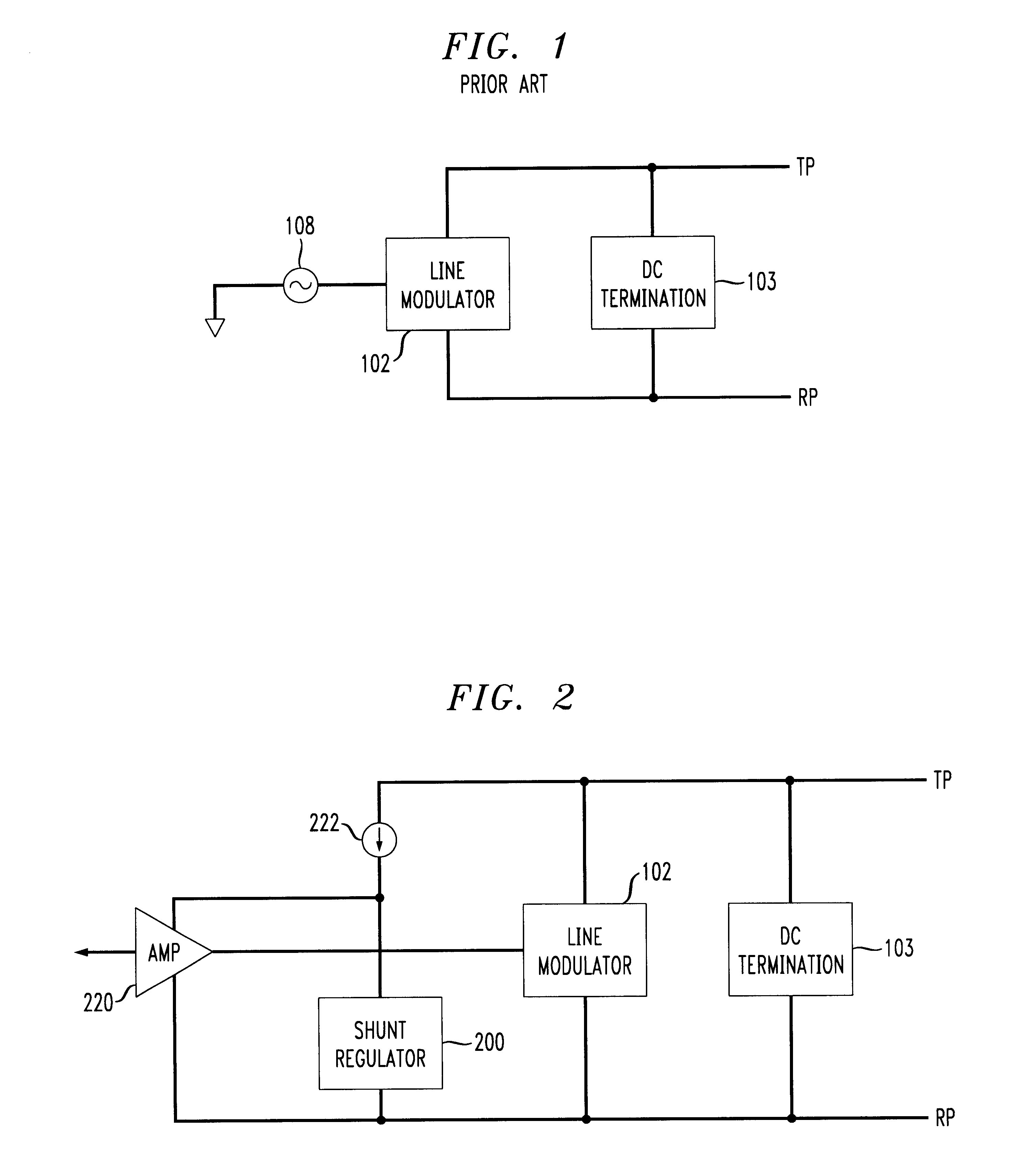
A suitable conventional DAA circuit is shown in FIG. 1. However, this DM does not provide power from the telephone line. Nevertheless, this conventional circuit typically exhibits low noise generation in the DAA because the tip polarity TP signal and ring polarity signal RP provide a common mode to both the line modulator 102 and the DC termination circuit 103 which are in parallel across the tip polarity signal TP and ring polarity sign...


PUM


Abstract

A telephone line interface or data access arrangement (DAA) is provided which draws power for the customer premises equipment from the telephone line. The DAA includes a shunt regulator as the power source drawing power from the telephone line, and a line modulator in series with the shunt regulator. A sense resistor is placed in series between the line modulator and shunt regulator to sense the line current. Accordingly, DC termination and AC modulation characteristics as presented by the DM to the telephone line can be adjusted by variation of an AC signal with DC offset input to the amplifier driving the line modulator without requiring a different DAA for use in regions or countries having various DC termination and AC modulation requirements. The differential feedback from a sense resistor reduces the noise induced in the circuit from the shunt regulator.

Description

1. Field of the InventionThis invention relates to a low noise telephone line interface for data access arrangements (DAA). More particularly, it relates to a line powered DAA having controllable DC termination and AC modulation.2. Background of Related ArtMany portable computer devices utilize modems and other data devices for communicating over a telephone line. In such devices, battery size and weight is an important consideration. A balance must be reached between the size and weight of the overall device, which is dictated largely by the choice of battery, and an acceptable length of operation between charges.Unfortunately, although operating an acceptable length of time when running typical application programs, the modems and other data communication devices of a portable computer utilize a large amount of power when communicating over a telephone line. The battery source which powers both the portable computer device and its modem is typically sized for general computing app...

Claims


Application Information

Patent Timeline
Patent Type & Authority Patents(United States)
IPC IPC(8): H04M19/00
CPCH04M19/001
Inventor HOLLENBACH, KEITH EUGENELATURELL, DONALD RAYMONDWITMER, STEVEN BROOKE
Owner LUCENT TECH INC
Learn More