Document reading apparatus

a document reading and document technology, applied in the direction of instruments, digital marking by punching, geometric image transformation, etc., can solve the problems of increased size, two-dimensional sensor type and main/sub-scan type, drawbacks in addition to increased size, etc., to improve operability and safety, the effect of improving the shap

Inactive Publication Date: 2004-05-18
HITACHI OMRON TERMINAL SOLUTIONS CORP
View PDF9 Cites 9 Cited by
  • Summary
  • Abstract
  • Description
  • Claims
  • Application Information

AI Technical Summary

Benefits of technology

to provide a document reading apparatus which is improved over the two-dimensional sensor type and main- / sub-scan type of document reading apparatuses suited for reading documents used in banks; which has improved operability and safety in putting a document in place; and which has an improved shape, compared with the conventional apparatus in which the head section protrudes over the face of the document impairing the appearance of the apparatus as well as the office.

Problems solved by technology

A scanner of the two-dimensional sensor type has a small number of two-dimensional sensor pixels and thus at present has difficulty in reading images at a resolution high enough to be able to optically recognize characters on a document.
The above-described types of the document reading apparatuses have a drawback of increased size because the document is fed or it is placed on a bed.
The two-dimensional sensor type and the main- / sub-scan type, too, have a drawback in addition to an increased size.
That is, the read head section, because it protrudes over the document face, can become an obstacle to an operator putting the document in place or pose a safety problem that the operator may hit against it.

Method used


Image

  • Document reading apparatus
  • Document reading apparatus
  • Document reading apparatus

Examples


first embodiment

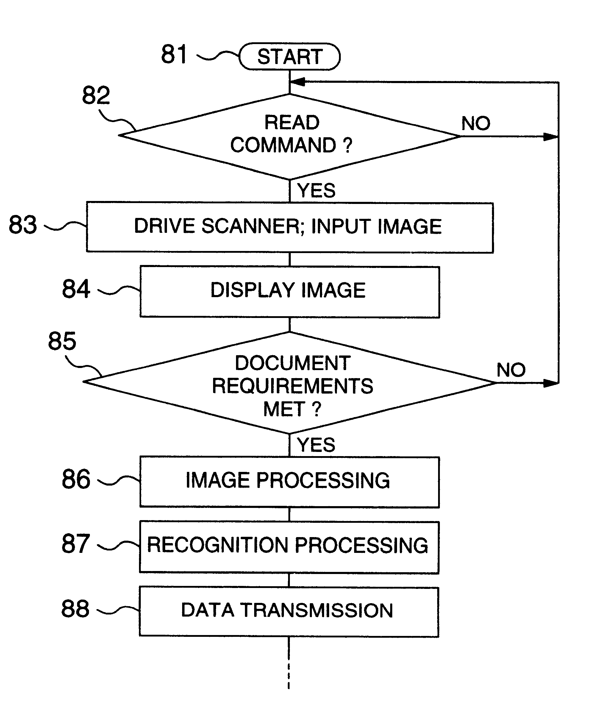
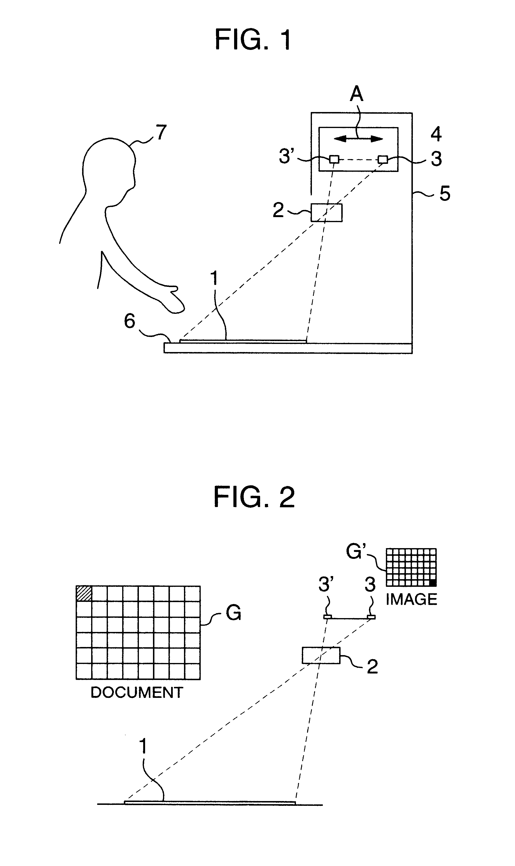
FIG. 1 shows a document reading apparatus according to the invention. This scanner employs a reading head section 4 which has a lens 2 located on a side opposite the operator 7 with respect to the center of the document 1. In this reading head section 4 the CCD sensor 3 is mechanically moved from a position 3 to a position 3' in a direction of arrow A relative to the stationary lens 2 to scan and read the entire surface of the document 1. The lens 2 according to this embodiment is preferably of a design in which an area where an image can be effectively focused (called an image circle) is large enough to produce a focused image of peripheral portions.

To read an image G of the document 1 through the lens 2, the scanner of this embodiment, as shown in FIG. 2, focuses on the CCD sensor 3 an image G' which is similar to the one-dimensional image sensor movement plane (from a position 3 to a position 3') and inverted horizontally and vertically. This image can be converted into a desired...

second embodiment

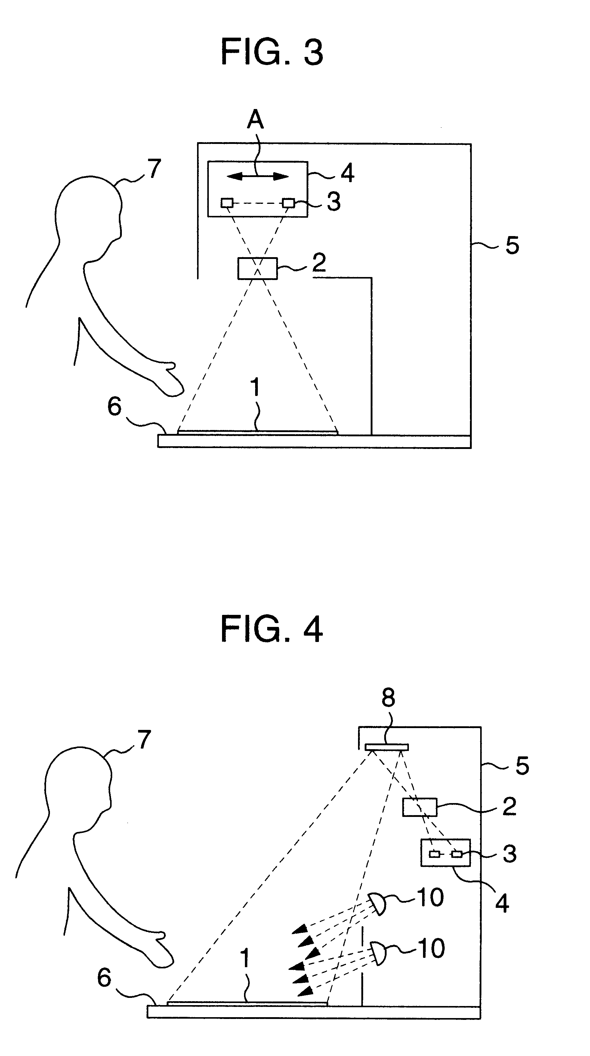
FIG. 4 shows a document reading apparatus which further develops the concept of the scanner of the previous embodiment. The scanner of this embodiment has a reflection mirror 8 installed at the top of a scanner case 5, a lens 2 and a reading head section 4 arranged below the reflection mirror 8, and a lamp 10 for illuminating the document 1.

In this document reading apparatus, the image of the document 1 is reflected by the reflection mirror 8 and, as in the preceding embodiment, the moving CCD sensor 3 scans and reads the entire surface of the document 1 through the lens 2.

Because of the reflection mirror 8, the document reading apparatus of this embodiment can reduce the height and therefore the size of the scanner. Further, because the illuminating lamp 10 can be incorporated in the scanner case 5, it is possible to enhance the reading precision and to construct the apparatus in an all-in-one structure.

Although the document reading apparatuses of these embodiments have been expla...

third embodiment

Next, a scanner according to the invention will be described by referring to FIG. 5. The scanner of the preceding embodiments can be designed under the assumption that the lens has a large image circle. The scanner shown in FIG. 5 can use a lens with an ordinary size of image circle while at the same time using a system in which the one-dimensional image sensor is moved.

The principle of the scanner of FIG. 5 uses an image reading section that has an optical system shown in FIG. 6, i.e., a so-called tilt type optical system in which an extended line L1 of an image plane of the document 1, an extended line L2 of the lens 2 perpendicular to the lens optical axis, and an extended line L3 of a light receiving plane of the CCD sensor 3 that senses an image intersect at one point P. The tilt type optical system has a characteristic that the original image H of the document 1 is received as a trapezoidal image H' by the CCD sensor 3 as shown. Hence, the scanner of this embodiment should pre...


PUM


Abstract

In reading an image of the document, the CCD sensor reads the image of the document through the image reading lens. The reading head including the image reading lens and the CCD sensor is arranged deviated from the center of the document reading area so that the reading head is removed from above the document. The image of the document read in is corrected by the image correction device, and the corrected image is displayed on the display.

Description

1. Field of the InventionThe present invention relates to a document reading apparatus for optically reading images on documents such as vouchers and forms, and more particularly to a document reading apparatus used in banking business that performs optical character recognition (OCR) on public money vouchers and payment / receipt slips and reads images on a variety of documents to input diagrammatic and line-drawn images.2. Description of Related ArtAmong document reading apparatuses designed to take in images on documents, including images of various kinds of vouchers and slips to be OCR-processed and images of seals, portraits and signatures on documents, there are mainly two types. One is a fixed sensor type in which an image sensor (line sensor) for optically reading a one-dimensional image is held immovable and a document is fed over the image sensor to read an image. Another is a flat bed scanner type in which a sensor is moved relative to a document placed on a bed to read an ...

Claims


Application Information

Patent Timeline
Patent Type & Authority Patents(United States)
IPC IPC(8): H04N1/10H04N1/04G06T1/00G06T3/00
CPCH04N1/04H04N1/1013H04N2201/0436
Inventor KANO, MITSUNARIKONISHI, YOSHIHARU
Owner HITACHI OMRON TERMINAL SOLUTIONS CORP
Why Eureka
Try Eureka