Wood drying method

a drying method and wood technology, applied in the direction of drying machines with progressive movements, lighting and heating apparatus, furnaces, etc., can solve the problem that the conventional method of drying wood by controlling the concentration of oxygen is not enough to efficiently achieve the effect of

Inactive Publication Date: 2004-06-01
TECHN SYST KEEP
View PDF7 Cites 7 Cited by
  • Summary
  • Abstract
  • Description
  • Claims
  • Application Information

AI Technical Summary

Problems solved by technology

However, the above conventional method for drying wood by controlling the concentration of the oxygen is insufficient to efficiently dry the wood in a short period of time and is required to be further improved.

Method used


Image

  • Wood drying method
  • Wood drying method
  • Wood drying method

Examples


Embodiment Construction

)

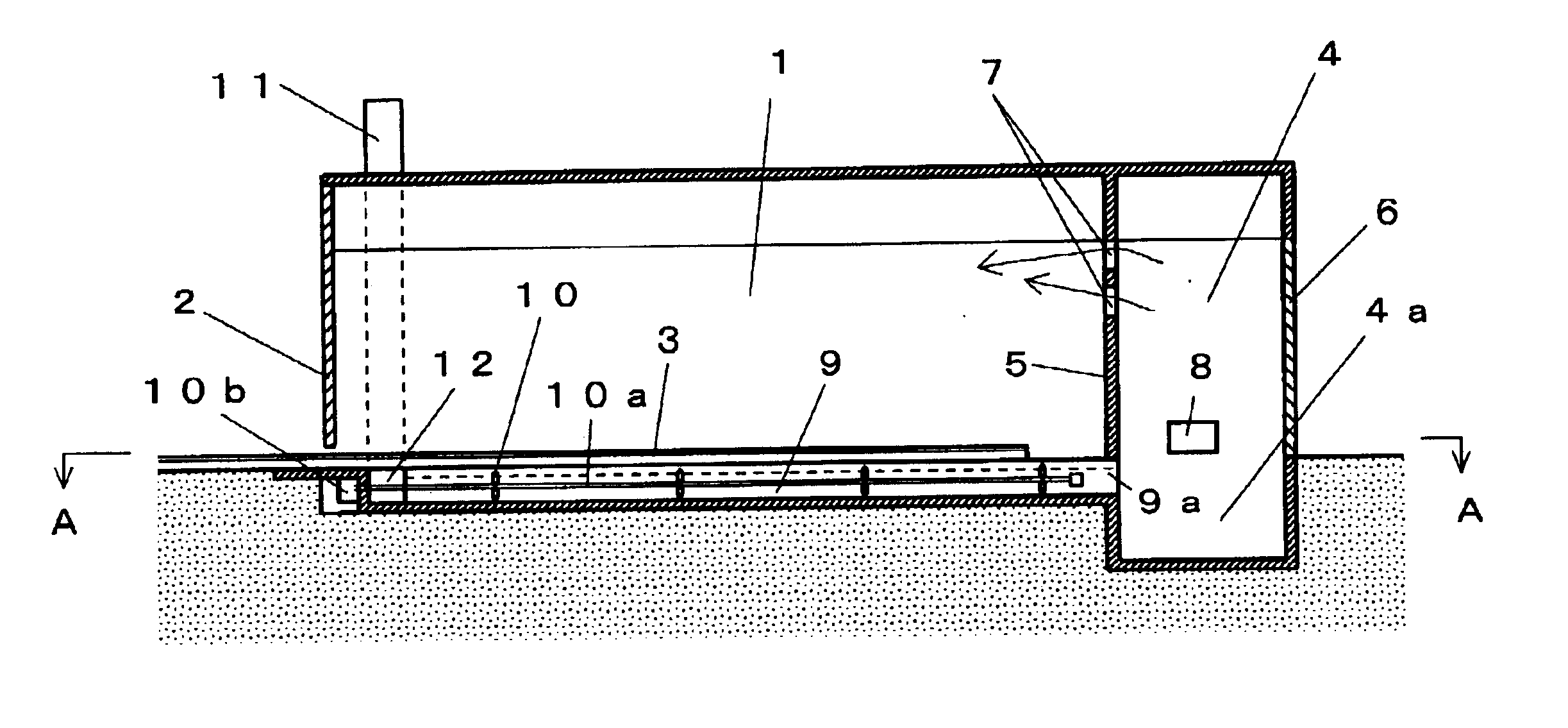
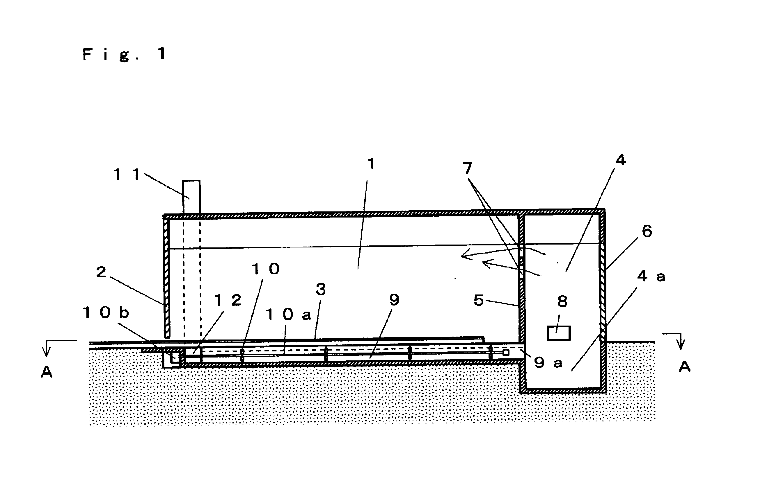
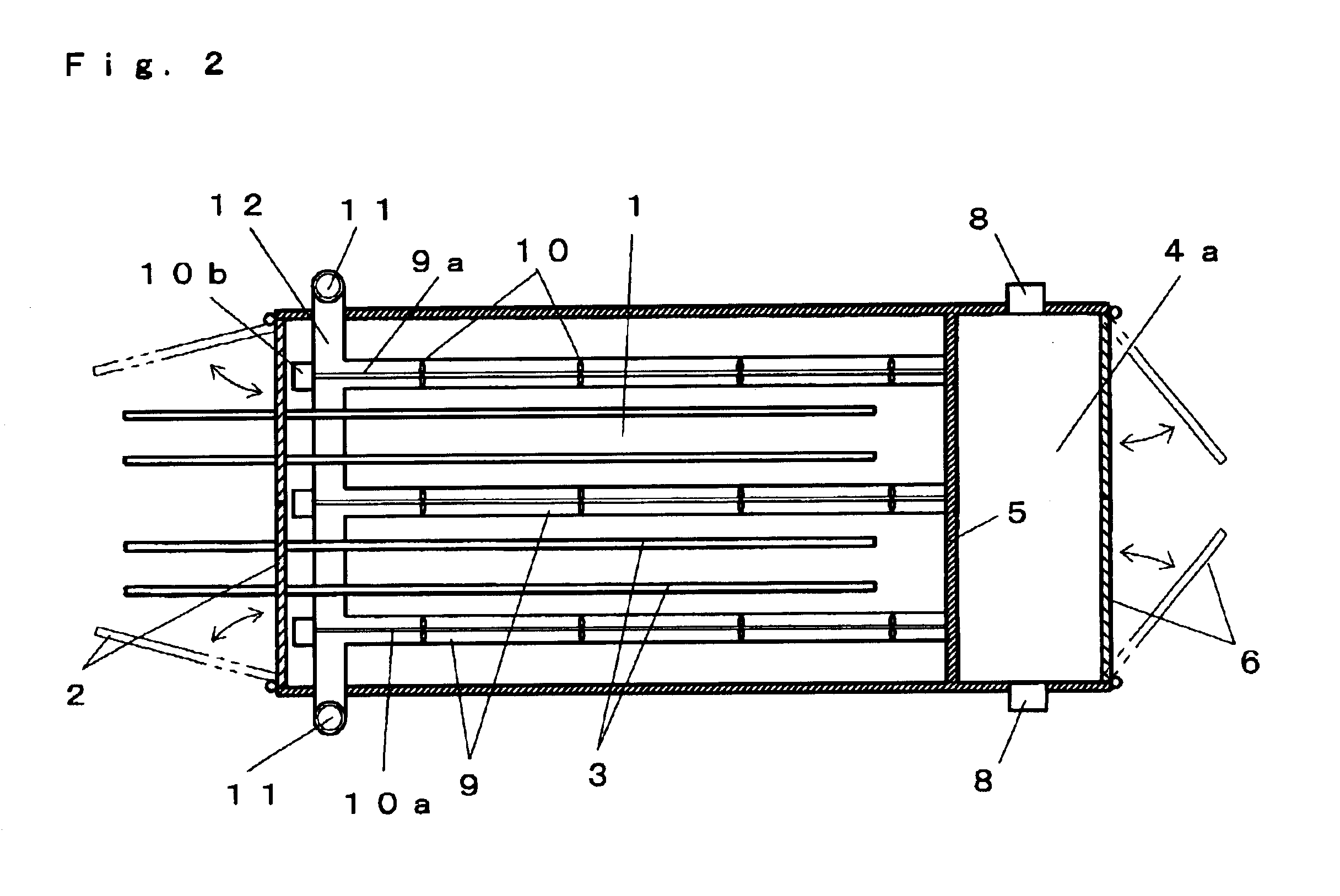
The present invention will now be described in detail with reference to the drawings showing an embodiment thereof.

In FIGS. 1 and 2, reference numeral 1 designates a drying room which houses green wood such as thinnings. Reference numeral 2 designates each of opening and closing doors which opens when the wood is put into and taken out from the drying room 1. Reference numeral 3 designates each of rails which is laid on a floor of the drying room 1 and extends to the outside from an entrance for wood, at which the opening and closing doors 2 are provided. The interior of the drying room 1 can be hermetically sealed when the opening and closing doors 2 are closed. A truck (not shown) travels on the rails 3, and the truck mounts thereon the wood. In this connection, the rails 3 and the truck are just examples of means for putting and taking out the wood into and from the drying room 1, and therefore the means are not confined to these examples.

Reference numeral 4 designates a combust...


PUM


Abstract

Method for drying wood in a short period of time by maintaining the concentration of a combustion gas contained in a drying room atmosphere for use in drying the wood to a high value and by maintaining the pressure of the drying room atmosphere to a high value. Wood fuels such as waste wood are put into a combustion chamber ins lower area of a combustion gas generating furnace and then the wood fuels are burned, followed by introducing the high-temperature combustion gas generated by the burning of the wood fuels into an upper area of a drying room housing the green wood to thereby dry the wood. Thermal drying of the wood is carried out by maintaining the concentration of the combustion gas present in the drying room atmosphere at a the high value and by maintaining the pressure of the drying room atmosphere at a high value.

Description

1. Field of the InventionThe present invention relates to a method for drying wood, and more particularly to a method for drying green wood such as thinnings, green bamboo or similar other green plants in a short period of time. In the present specification, the term "wood" includes the bamboo and other green plants.2. Description of the Prior ArtConventionally, there are proposed various methods for drying wood including a method in which green wood is put in a drying room to be sealed, and wood fuels such as waste wood are put into a combustion chamber provided in a lower area of a combustion gas generating furnace to be sealed and then the wood fuels are burned, followed by introducing a high-temperature combustion gas generated by the burning into an upper area of the drying room, to thereby dry the wood, wherein the concentration of the oxygen in the drying room is maintained to a low level.According to the above-mentioned conventional method for drying wood, the wood can be dr...

Claims


Application Information

Patent Timeline
Patent Type & Authority Patents(United States)
IPC IPC(8): F26B21/14F26B21/10F26B23/02F26B21/06F26B23/00F26B3/04
CPCF26B21/10F26B21/14F26B23/028F26B23/02
Inventor ISHII, SACHIO
Owner TECHN SYST KEEP
Why Eureka
Try Eureka