Surface texture measuring machine, leveling device for surface texture measuring machine and orientation-adjusting method of workpiece of surface texture measuring machine
a technology of surface texture and measuring machine, which is applied in the direction of mechanical measuring arrangement, instruments, manufacturing tools, etc., can solve the problems of affecting the accuracy of measurement, increasing the size of the measuring machine, and complicating the device structur
- Summary
- Abstract
- Description
- Claims
- Application Information
AI Technical Summary
Benefits of technology
Problems solved by technology
Method used
Image
Examples
first embodiment
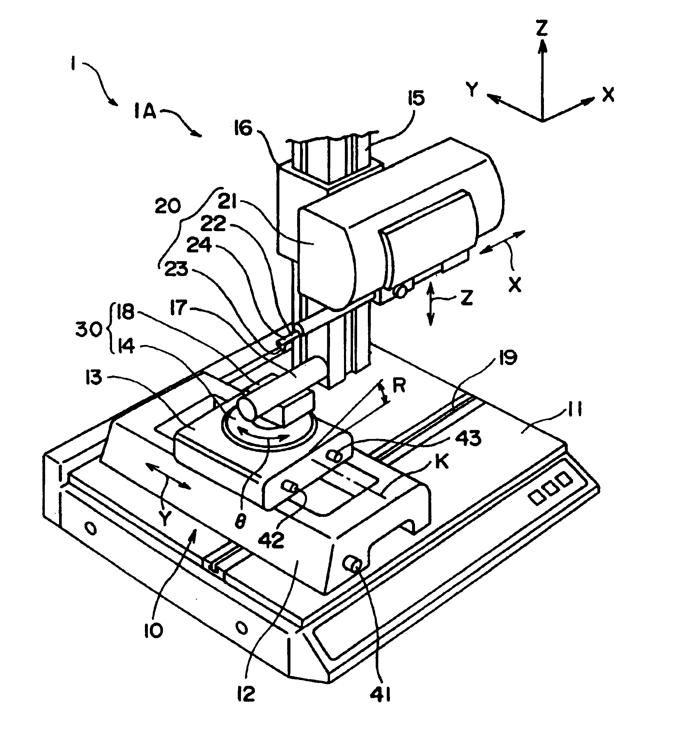
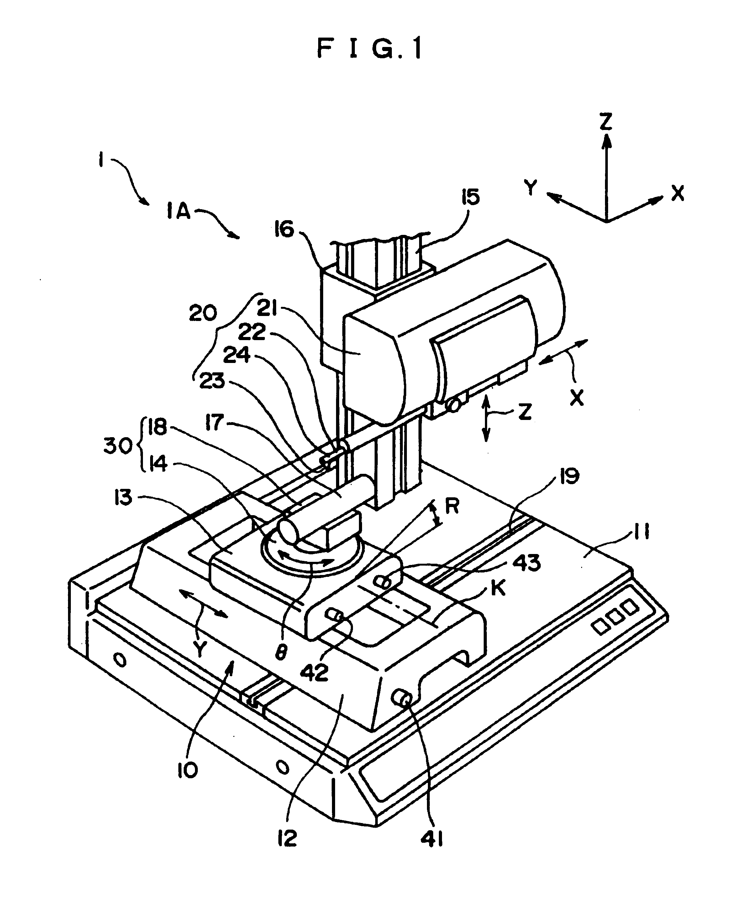
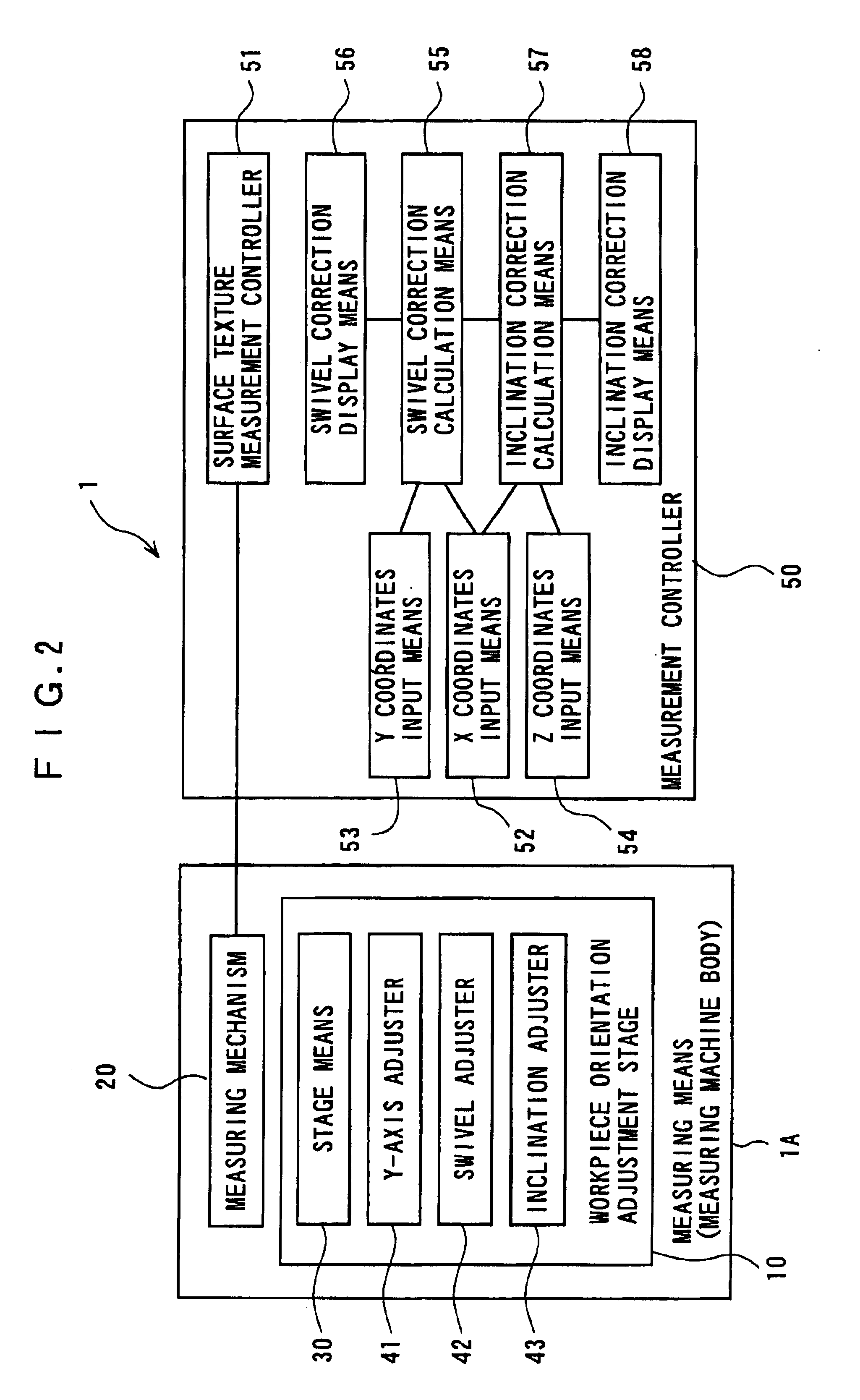
As shown in FIG. 1, a measuring machine body 1A as a measuring means of a surface texture measuring machine 1 according to first embodiment of the present invention has a base 11.
A workpiece orientation adjustment stage 10 is provided on the base 11, the workpiece orientation adjustment stage 10 having a Y-axis stage 12 capable of moving in Y-axis direction (a direction orthogonal with X-axis direction [measurement direction] on a horizontal plane), a R-axis stage 13 provided on the Y-axis stage 12 and being capable of seesawing in R-axis direction (a direction orthogonal with the X-axis direction on a perpendicular plane), and a rotary stage 14 provided on the R-axis stage 13 and being rotatable in .theta. direction. Further, a column 15 stands on a right side of the rear of the base 11 as illustrated, the column 15 having a Z-axis slider 16 vertically movable along Z-axis direction. A measuring mechanism 20 is provided to the Z-axis slider 16 movably in X-axis direction (measureme...
second embodiment
Next, second embodiment of the present invention will be described below with reference to FIGS. 9-13.
The present embodiment is directed to an leveling device 60 provided to the surface texture measuring machine 1 of the above-described first embodiment for measuring the inclination of the workpiece 17 by the measuring mechanism 20 and accurately adjusting the orientation of the workpiece based on the measurement data. In other words, the leveling device 60 according to the present embodiment corresponds to the stage means 30 having the R-axis stage 13 and the inclination Digimatic micrometer head 43, and can be held on the base 11 in place of the stage means 30.
As shown in FIG. 9, the leveling device 60 has a operation amount calculation means 63 for calculating a operation amount for inclination adjustment based on information from a displacement detecting means 61 and moving means 62, an output means 64 for displaying, or printing, or data-outputting the calculated operation amou...
third embodiment
Next, third embodiment of the present invention will be described below with reference to FIG. 14.
In the present embodiment and below-described fourth and fifth embodiments, the same reference numeral will be applied to the same component as in the above-described second embodiment to omit or simplify detailed explanation thereof.
An leveling device 80 of the present embodiment has an inclination adjustment means 85 composed of an absolute micrometer head 81 having an inclination piece 82 at a distal end thereof, the micrometer head 81 being attached to a holder 79.
Specifically, the inclination piece 82 is connected to the distal end of the absolute micrometer head movably in arrowed X direction and has a inclined surface on a side in contact with the point-of-action member 73 declined toward the micrometer head 81. Accordingly, when the knob of the micrometer head 81 is manually rotated, the inclination piece 82 is moved back and forth, so that the point-of-action member 73 is verti...
PUM
 Abstract
Description
Claims
Application Information
 - R&D
- Intellectual Property
- Life Sciences
- Materials
- Tech Scout
- Unparalleled Data Quality
- Higher Quality Content
- 60% Fewer Hallucinations
Browse by: Latest US Patents, China's latest patents, Technical Efficacy Thesaurus, Application Domain, Technology Topic, Popular Technical Reports.
© 2025 PatSnap. All rights reserved.Legal|Privacy policy|Modern Slavery Act Transparency Statement|Sitemap|About US| Contact US: help@patsnap.com


