

Cap device
a technology of cap and seal, applied in the direction of caps, liquid handling, sealing, etc., can solve the problems of affecting the operation of the cap, affecting the sealing effect, and not easy to use, so as to improve the ease of opening/closing
Inactive Publication Date: 2004-06-08
TOYODA GOSEI CO LTD
View PDF13 Cites 63 Cited by
- Summary
- Abstract
- Description
- Claims
- Application Information
AI Technical Summary
Benefits of technology
The cap device maintains a tight seal under external forces and provides ease of operation with minimal space requirements, allowing the handle to turn freely if subjected to external forces, thus preventing seal loss and improving attachment and detachment ease.
Problems solved by technology
However, the cap has the drawback that when attaching or detaching the fuel gap, it is difficult to discern how it should be operated, i.e., that pressing the actuating button allows the cap to be attached or detached, and is thus not easy to use.
Because the actuating button is located on the handle, the handle needs to be larger, which has the drawback of requiring a larger space to accommodate it around the opening of the tank.
With the handle in the retracted position, the first clutch unit and second clutch unit turn freely in the opening direction, preventing the casing main body from turning under external force and resultant loss of seal.
The reason is that amounts of less than 1 wt % do not give electrical conductivity, whereas in excess of 30 wt % the resin becomes highly viscous in injection molding process of the cover 40, possibly resulting in injection molding defects due to metal filler clogging or pooling.
Further, where only a single resin spring is used to generate rotational torque over a wide control range it will be necessary for the resin spring to flex appreciably, which over a period of several years may lead to failure.
Method used
View moreImage
Smart ImageViewing Examples

Examples
Embodiment Construction
has been provided for the purpose of explaining the principles of the invention and its practical application, thereby enabling others skilled in the art to understand the invention for various embodiments and with various modifications as are suited to the particular use contemplated. The foregoing detailed description is not intended to be exhaustive or to limit the invention to the precise embodiments disclosed. Modifications and equivalents will be apparent to practitioners skilled in this art and are encompassed within the spirit and scope of the appended claims.
Login to View More PUM
 Abstract
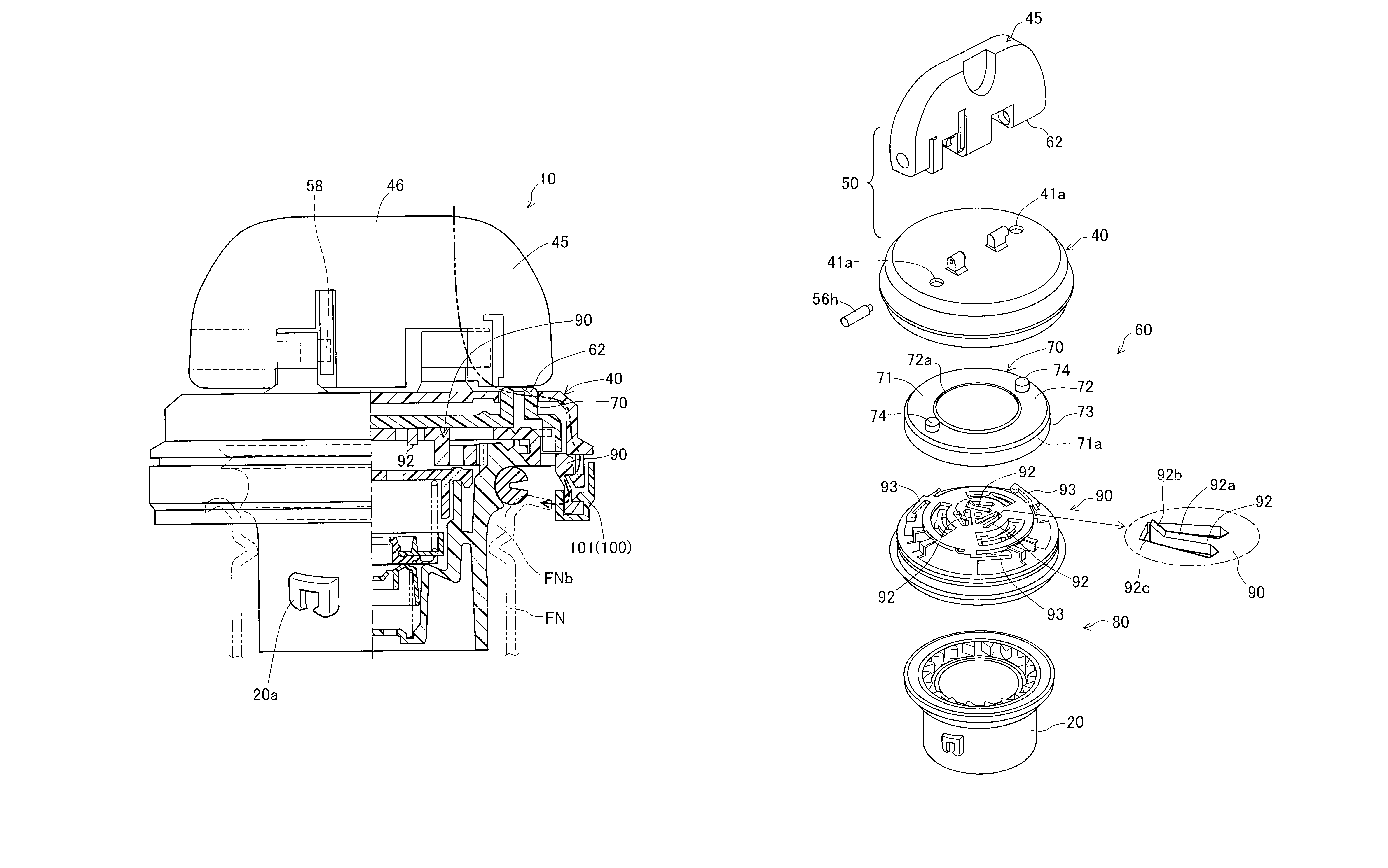
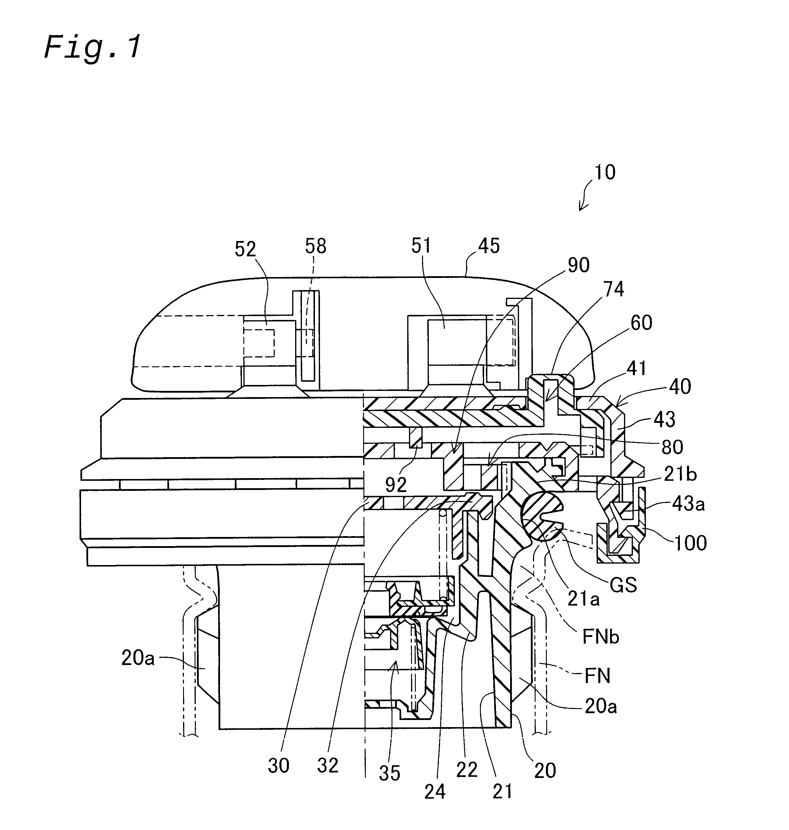
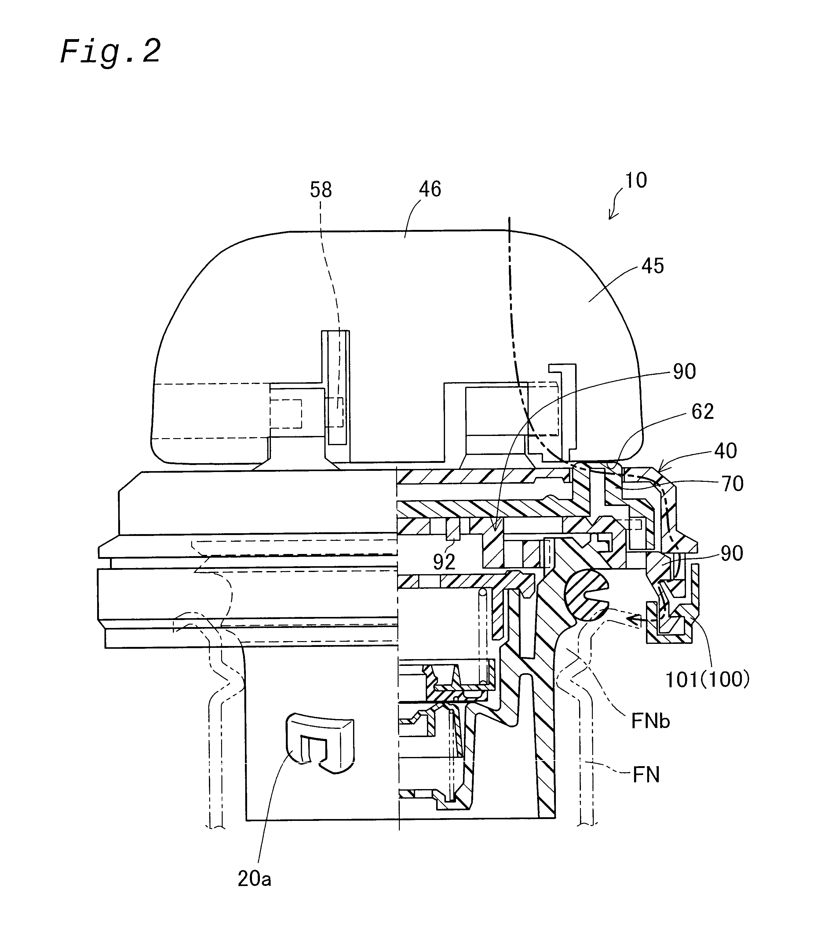
A fuel cap 10 maintains high sealing even when subjected to external force; is easy to operate; and requires minimal space for accommodation. The cap device comprises a casing body 20 for closing the filler opening FNb in a sealed condition, a cover 40, a handle 45, a clutch mechanism 60 and a torque transmission mechanism 80. By upraising the handle to the handling position and applying rotational torque, rotational torque is transmitted to the casing body 20 via the clutch mechanism 60 and the torque transmission mechanism 80, closing the filler opening FNb. The handle 45 lowers back to the retracted position when released, whereupon the clutch mechanism 60 assumes non-transmission mode wherein the cover 40 and the handle 45 rotate freely if subjected to external force such as in a collision.
Description
This application claims the benefit of and priority from Japanese Applications No. 2001-359110 filed Nov. 26, 2001 and No. 2002-212785 filed Jul. 22, 2002, the contents of which are incorporated herein by reference.1. Field of the InventionThe present invention relates to a cap device for detachable attachment to a opening member of a fuel tank.2. Description of the Related ArtOne example of a conventional tank cap devices is disclosed in U.S. Pat. No. 4,830,058. The fuel cap comprises an outer shell having a gasket attached for providing closure to the opening of a filler neck; a cover having a handle and mounted on the outer shell; and an interconnecting mechanism between the outer shell and cover for switching between a transmission mode, in which rotational torque of the cover is transmitted, and a non-transmission mode in which same is not transmitted. The interconnecting mechanism is provided with an actuating button exposed at the top face of the handle; by pressing the actua...
Claims
Login to View More Application Information
Patent Timeline
 Patent Type & AuthorityPatents(United States)
IPC IPC(8): B60K15/04
CPCB60K15/0406B60K2015/03401Y10S220/33
InventorHAGANO, HIROYUKINAKAGAWA, MASAYUKI
OwnerTOYODA GOSEI CO LTD