
Capillary optical element with a complex structure of capillaries and a method for its manufacture

a technology of optical elements and capillaries, applied in the direction of glass shaping apparatus, decorative surface effects, decorative arts, etc., can solve the problems of direct transmission of high-energy radiation through, requiring more or less uniform transmission, and enhancing transmission efficiency only over a relatively narrow energy rang

Inactive Publication Date: 2004-06-15
IFG INST FOR SCI INSTR
View PDF7 Cites 10 Cited by
  • Summary
  • Abstract
  • Description
  • Claims
  • Application Information

AI Technical Summary

Benefits of technology

"The invention is a capillary optics with a complex structure of capillaries that can be used in various applications such as diffractometry, micro-diffractometry, x-ray fluorescent analysis, and photoelectron spectroscopy. The capillaries are designed to capture and increase the intensity of x-rays by several orders of magnitude. The optimal energy range for transmission through the capillaries depends on the diameter of the capillaries, and there is a trade-off between transmission and focus. The invention provides a solution for improving the transmission efficiency over a wide energy range by taking into consideration both factors mentioned above."

Problems solved by technology

However, the solution proposed therein has the disadvantage that the transmission efficiency is enhanced only over a relatively narrow energy range.
Many practical application, however, require a more or less uniform transmission over a wide energy range.
Another disadvantageous effect, aside from the effect due to inhomogeneous transmission, results from a direct transmission of high-energy radiation through the lens as a whole and through the thin walls of the capillaries.
This undesirable side effect makes it difficult, for example in x-ray fluorescent analysis, to unambiguously localize the heavy elements whose characteristic lines are excited by high-energy radiation.

Method used


Image

  • Capillary optical element with a complex structure of capillaries and a method for its manufacture
  • Capillary optical element with a complex structure of capillaries and a method for its manufacture
  • Capillary optical element with a complex structure of capillaries and a method for its manufacture

Examples


Embodiment Construction

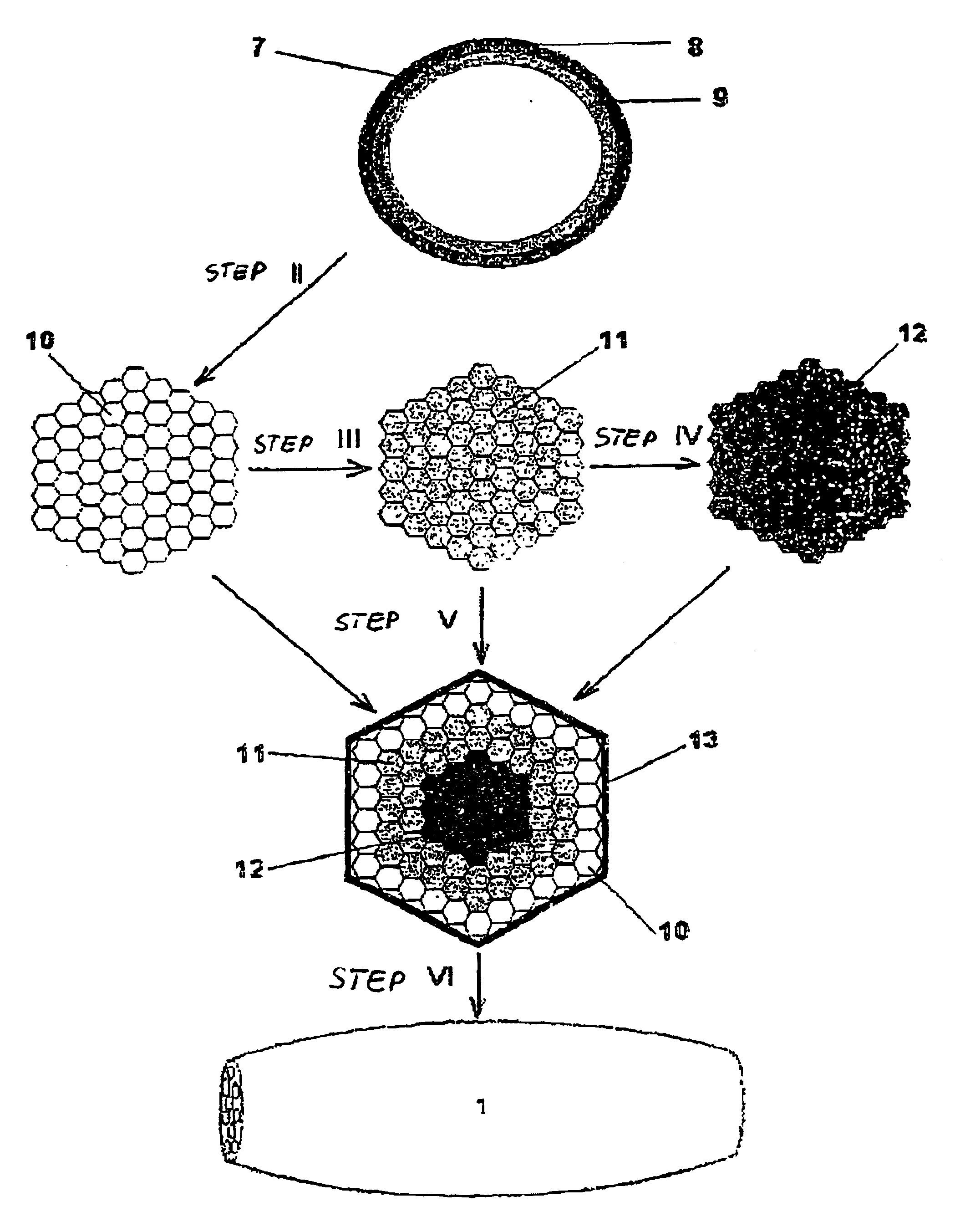
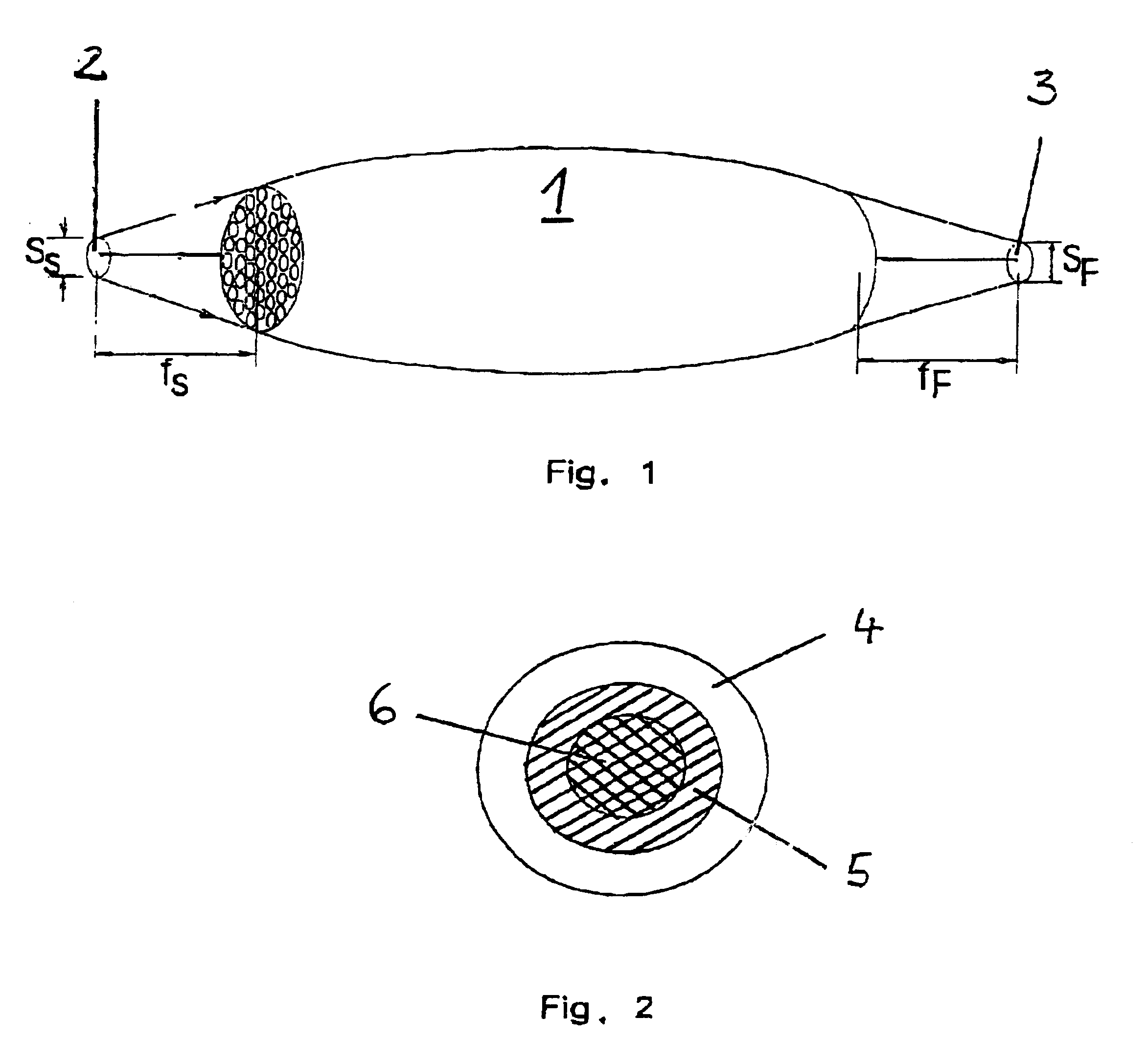
To achieve a uniform transmission, the present embodiment employs a lens embodied as a capillary optical element which has a complex structure of channels with different dimensions. The channels of small dimension are effective in the range of high energies, channels with intermediate dimensions are intended for the intermediate energy range, whereas channels with large dimensions are used in the low energy range.

The angular aperture of the lens is greater at lower energies than at higher energies, because at lower energies the angle for total reflection is greater than at higher energies. Moreover, the number of reflections for deflecting the radiation is also greater at higher energy, causing higher losses. With increasing distance from the optical axis of the lens, the intensity of the radiation component at higher energy decreases faster than the intensity of the radiation component at lower energy. The distribution of the radiation over the cross section of the lens in the radi...


PUM

PropertyMeasurementUnit
aperture angleaaaaaaaaaa
critical angle φcaaaaaaaaaa
sizeaaaaaaaaaa

Abstract

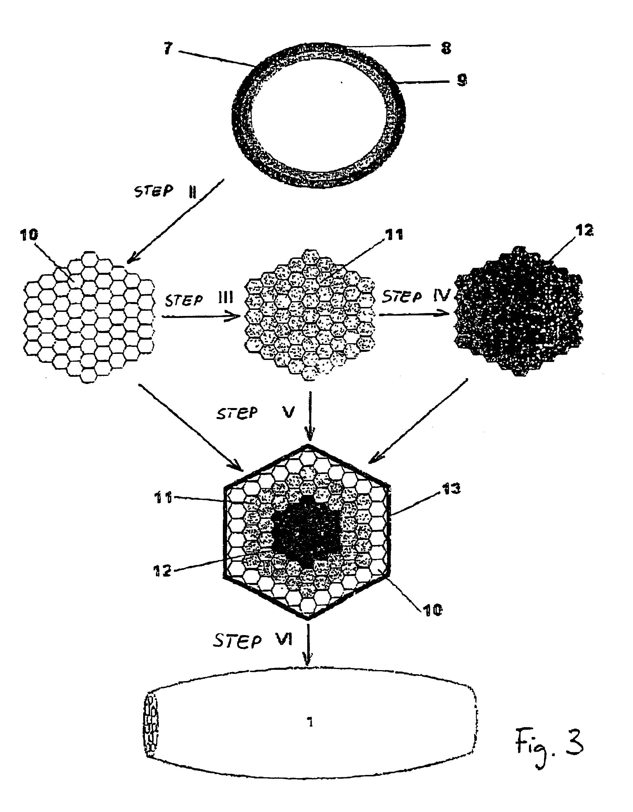
The invention describes a capillary optical element with a complex structure of capillaries and a method for its manufacture. To achieve uniform transmission, for example, a lens can be used as a capillary optical element which has a complex structure with channels of different diameter. The channels with the smaller diameter operate effectively at higher energies, channels with intermediate diameters are intended for an intermediate energy range, whereas channels with a large diameter are used in a low energy range. A lens can consist, for example, of three zones: channels with small diameter are used in the central zone, channels with intermediate diameters are used in the intermediate annular zone, and the peripheral zone has channels of large diameters. The number of zones can arbitrary. In addition, a technical process for manufacturing the complex capillary structures is described.

Description

1. Field of the InventionThe invention relates to a capillary optical element with a complex structure of capillaries and a method for its manufacture. The capillary optical element can be used, for example, in diffractometry, micro-diffractometry, x-ray fluorescent analysis, micro-x-ray fluorescent analysis, and in photoelectron spectroscopy. In all these cases, the light intensity can be increased by several orders of magnitude.2. Description of the Related ArtPoly-capillary optics has emerged over the past decade as a new important field in x-ray optics. The underlying principle of poly-capillary optics is the channeling of x-rays through multiple total internal reflection on the interior walls of glass capillaries. Curved as well as straight capillaries conduct x-rays along their respective axes. In this way, the propagation direction of the x-rays can be directly influenced.A bundle of specially formed glass capillaries which are combined into a monolithic structure forms a so-...

Claims


Application Information

Patent Timeline
Patent Type & Authority Patents(United States)
IPC IPC(8): C03B37/025C03B37/02C03B23/00C03B23/047C03B37/075C03B37/027G21K1/00G21K1/06
CPCC03B23/047C03B37/025C03B37/027C03B37/0756G21K1/06
Inventor BJEOUMIKHOV, ANIOUAR
Owner IFG INST FOR SCI INSTR
Learn More