
Brushless DC motor

a brushless dc motor and motor technology, applied in the direction of mechanical energy handling, magnetic circuit rotating parts, magnetic circuit shape/form/construction, etc., can solve the problems of increased structural complexity, increased structure complexity, and increased cost of structur

Inactive Publication Date: 2004-06-22
MITSUBISHI ELECTRIC CORP
View PDF21 Cites 54 Cited by
  • Summary
  • Abstract
  • Description
  • Claims
  • Application Information

AI Technical Summary

Problems solved by technology

This structure is not only expensive but in addition requires a housing for storing the control circuit section and additional space for arranging the housing.
However, the problem of heat damage on the control circuit section due to heat generated by the coils is not avoided.
As a result, structural complexity is increased, freedom of design with respect to component shape is limited and manufacturing costs increase.
Furthermore, since large temperature variations result from generation of heat by the coils in a tightly-closed motor, it is sometimes the case that a breathing phenomenon is generated due to a pressure difference between the atmospheric pressure and the pressure in the motor.
For example, when moisture enters into the motor as a result of the breathing, the possibility exists that short circuits or insulation failure may result from the moisture entering into the control circuit section.

Method used


Image

  • Brushless DC motor
  • Brushless DC motor
  • Brushless DC motor

Examples


embodiment 1

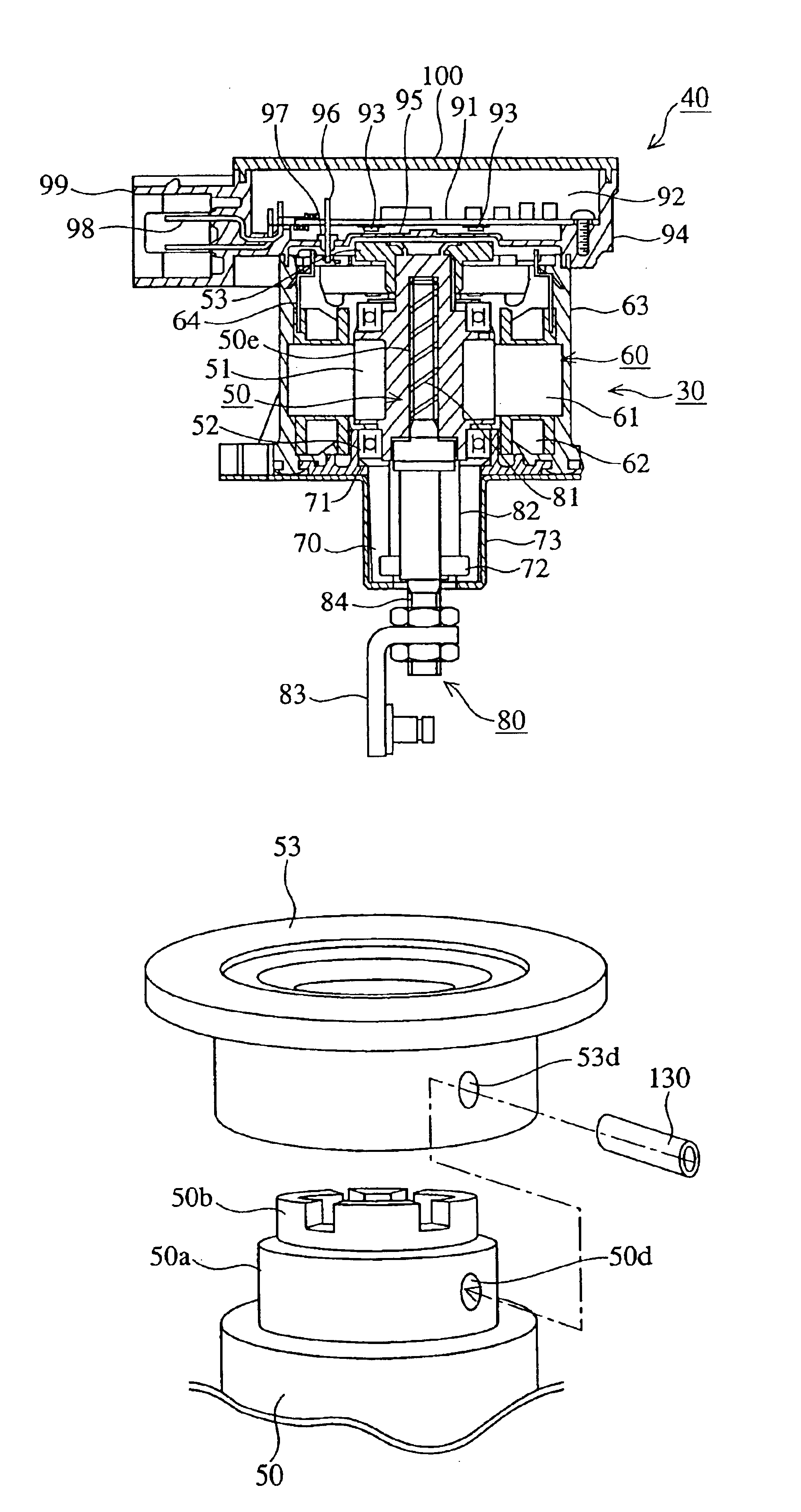
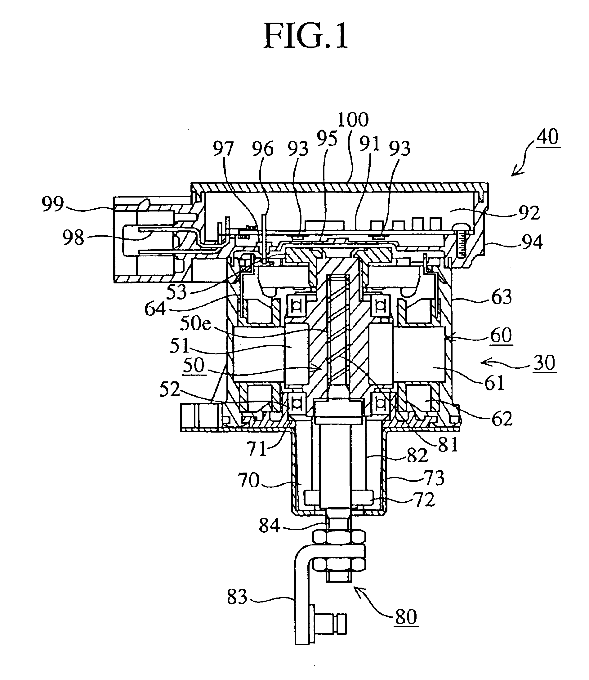
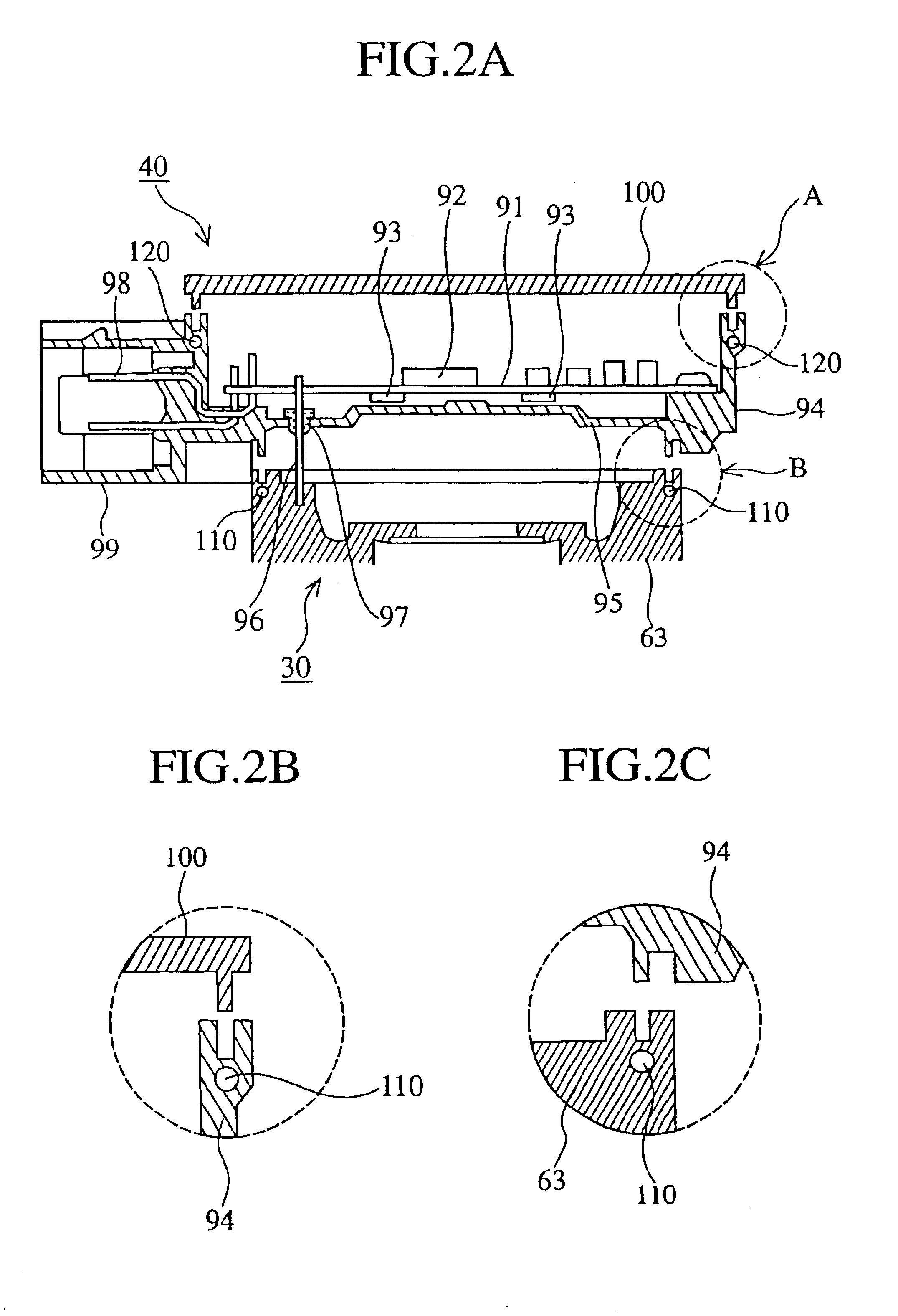
FIG. 1 shows an axial sectional view of a brushless DC motor according to a first embodiment of the present invention. In the figure, reference numeral 30 denotes a motor section, 40 is a control circuit section, 50 is a rotor, 51 is a first permanent magnet, 52 is a bearing, and 53 is a second permanent magnet. The first permanent magnet 51 is magnetized with the plural magnetic poles and is disposed on an outer peripheral face of the rotor 50. The bearings 52 are arranged on both end sides of the first permanent magnet 51 so as to sandwich the first permanent magnet 51. Furthermore, the second permanent magnet 53 is attached on an opposite side to the output side of the rotor 50.

The rotor 50 is made of a PPS resin, a threaded hole is provided in the central axial portion of the rotor 50. The first permanent magnet 51 is of a ferritic magnet and is integrally formed on the outer periphery of the rotor 50 with the insert molding. The second permanent magnet 53 is formed with a neody...


PUM


Abstract

A brushless DC motor includes: a motor section which has a rotor, a stator and a housing; a control circuit section which is integrated with the motor section and separated from the motor section by a partition; and a casing member which covers the control circuit section to isolate the control circuit section from the external environment. A position detection means is disposed outside of a bearing member with respect to an axial direction.

Description

1. Field of the InventionThe present invention relates to a brushless DC motor used as a driving source for a moveable vane of a VG Variable Geometric) turbo system, an EGR (exhaust gas recirculation system) valve or a throttle valve used in on-vehicle equipment.2. Description of Related ArtA conventional brushless DC motor, as disclosed for example in JP-A-11-346497, is constituted by a rotor which retains a permanent magnet having magnetic poles on an outer periphery, a bearing portion which rotatably supports the rotor, a stator with current-carrying coils wound thereon which is disposed on an outer side of the rotor, a rotation position detection means which switches the power supply to the plurality of coils retained on the stator in accordance with the position of the rotor, a housing which stores the above components, and a control circuit for controlling the drive operation of the motor.The structure of a general brushless DC motor similar to the above motor will be describe...

Claims


Application Information

Patent Timeline
IPC IPC(8): H02K29/06H02K5/16H02K29/08H02K11/04H02K1/27H02K5/10H02K5/22H02K11/30H02K21/14
CPCH02K5/161H02K29/08H02K11/0073H02K11/33
Inventor DOI, HIROFUMISEKIYA, MUTSUO
Owner MITSUBISHI ELECTRIC CORP
Features
  • Generate Ideas
  • Intellectual Property
  • Life Sciences
  • Materials
  • Tech Scout
  • Unparalleled Data Quality
  • Higher Quality Content
  • 60% Fewer Hallucinations
Learn More