Printer device alignment method and apparatus

a printing device and alignment method technology, applied in the direction of printing mechanisms, instruments, transportation and packaging, etc., can solve the problems of misregistration between, too much ink to be deposited in some areas, too little ink to be deposited in other areas

Inactive Publication Date: 2004-06-29
HEWLETT PACKARD DEV CO LP
View PDF12 Cites 48 Cited by
  • Summary
  • Abstract
  • Description
  • Claims
  • Application Information

AI Technical Summary

Benefits of technology

Advantageously, this method also provides for a correction for any errors introduced into the offset measurement process that might be caused by skewing of the print media between the steps of printing and scanning the alignment pattern. Thus, this embodiment makes the invention highly suited to printer devices which have a scanner located at a different point on the media path to the printheads; for example downstream.

Problems solved by technology

The mechanical misalignment of a printhead may result in an offset in the positioning of ink drops on the print media.
If each printhead in a printer is not sufficiently accurately aligned with the remaining printheads of the printer, a misregistration between the images formed by the different coloured ink drops on the print media may result.
This may cause too much ink to be deposited in some areas and too little ink to be deposited in others.
This often gives rise "grainy" appearance in the printed image.
This type of print error is often particularly noticeable to the viewer.
Consequently, such misregistrations are generally unacceptable, with colour printing typically requiring image registration accuracy from each of the printheads of 1 / 2400 inch.
However, the spacing of the lines of the two alignment patches is slightly different, thus giving rise to an interference pattern.
This technique suffers from the disadvantage that it is relatively slow, being non-automated and reliant upon an operator.
Furthermore, the process is less suitable for use in printers having more than two printheads, due to the increased difficulty of determining the relative offsets for a greater number of printheads.
Although this system functions satisfactorily, the process which it employs is relatively slow, since the print media must be fed backwards and then forwards again in order to measure the position of each of the alignment patches.
Additionally, this system suffers from a further problem in that it can only be used with printer mechanisms that are capable of feeding the print media in both a forwards and a reverse feed direction.
Thus, this technique is generally not applicable to printers in which the reverse feed direction of the media feed motor is used to perform other functions, such as powering a duplexing mechanism.

Method used


Image

  • Printer device alignment method and apparatus
  • Printer device alignment method and apparatus
  • Printer device alignment method and apparatus

Examples


first embodiment

System of the First Embodiment

A typical application for the invention is in a large format colour inkjet printer. Commonly assigned U.S. Pat. No. 5,835,108, entitled "Calibration technique for misdirected inkjet printhead nozzles", describes an exemplary system which can employ aspects of this invention and the entire contents of which are incorporated herein by reference.

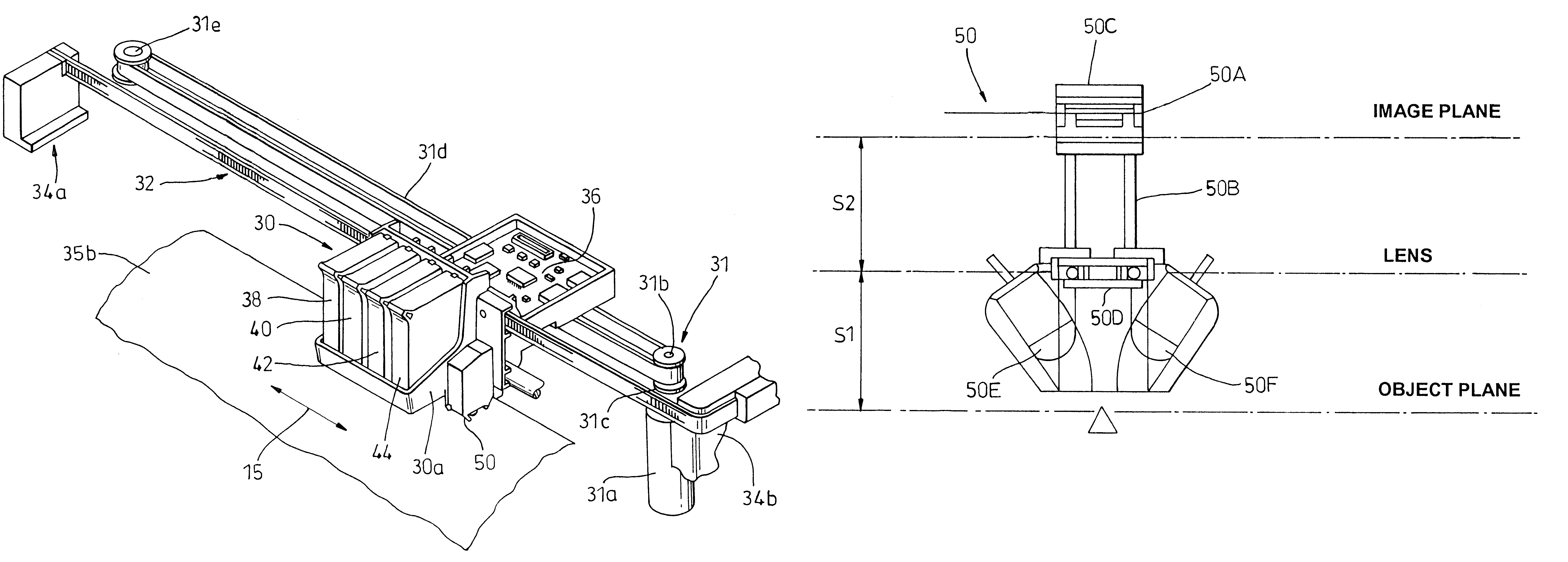
Referring now to FIG. 3, the system of the present embodiment will now be described. The figure shows a perspective view of an inkjet printer 10 having a housing 12 mounted on a stand 14. The housing has left and right drive mechanism enclosures 16 and 18. A control panel 20 is mounted on the right enclosure 18. A print medium 33 such as paper is positioned along a vertical or media axis by a media axis drive mechanism (shown in FIG. 5). As used herein, the media axis is called the X-axis denoted as 13, and the scan axis is called the Y-axis denoted as 15.

A carriage assembly 30, illustrated in phantom under a cover...

second embodiment

The second embodiment employs similar apparatus and methods to that described with respect to the first embodiment, thus corresponding apparatus and method steps will not be described further in detail.

Referring to FIGS. 10a and 10b, the method of the second embodiment will now be described. Features in FIGS. 10a and 10b which correspond to features described in the first embodiment are referenced with corresponding numerals.

As was described in the first embodiment, the printer carriage assembly 30 is controlled by the printer control unit of the printer to traverse the print media 33 along the scan axis 15 as in a normal printing mode. As the printer carriage assembly 30 traverses the print media 33, three test patterns 70, 71 and 72 are printed. These are shown in FIG. 10a. The first and third test patterns 70 and 72 are printed by a single reference printhead; in this example this is the black printhead 38. The second test pattern 71 is printed by a different printhead, the offse...


PUM


Abstract

A method of determining a registration offset in a hard copy apparatus, the apparatus comprising a pen arranged to mark a print medium and a sensor arranged to detect marks on the medium along a sensor path, the method comprising the steps of: marking a alignment pattern on the medium, the pattern being at least partially located along the sensor path; detecting the position along the sensor path of a portion of the pattern; and, determining a distance by which the pattern is offset from the sensor path in a direction substantially perpendicular to the sensor path, the pattern being configured such that the detected position is indicative of the offset distance.

Description

The present invention relates to printer devices, and particularly, although not exclusively, to a method and apparatus for determining and correcting misalignments between printheads in ink jet devices.BACKGROUND TO THE INVENTIONIt is known to produce paper copies, also known as "hard" copies of files stored on a host device, e.g. a computer using a printer device. The print media onto which files may be printed includes paper and clear acetates for use in lectures, seminars and the like.Referring to FIG. 1, there is illustrated a conventional host device 1, in this case a personal computer, linked to a printer device 2 via a cable 3. Amongst the known methods for printing text or graphics and the like onto a print media such as paper it is known to build up an image on the paper by spraying drops of ink from a plurality of nozzles.Referring to FIG. 2, there is illustrated schematically part of a prior art printer device comprising an array of printer nozzles 4 arranged into parall...

Claims


Application Information

Patent Timeline
Patent Type & Authority Patents(United States)
IPC IPC(8): B41J2/21B41J29/393B41J11/42B41J2/01B41J19/18B41J21/00B41J21/16B65H7/06
CPCB41J2/2135B41J29/393
Inventor CASTANO, JORGETOUSSAINT, DAVID
Owner HEWLETT PACKARD DEV CO LP
Why Eureka
Try Eureka