Medical valve with positive flow characteristics

Inactive Publication Date: 2006-09-21
FANGROW THOMAS F JR +3
View PDF99 Cites 37 Cited by
  • Summary
  • Abstract
  • Description
  • Claims
  • Application Information

AI Technical Summary

Benefits of technology

[0018] The valve of the present invention has a fluid space which expands upon connection of the second medical implement and contracts upon disconnection of the medical implement. When the valve is connected to a catheter, disconnection of the second medical implement creates a positive fl

Problems solved by technology

Unfortunately, prior art valves suffer from a problem arising from the disconnection of these medical implements from the valve.
A problem arises when the medical implement is disconnected from the valve.
In the medical setting, this movement of fluid is very undesirable.
A serious problem may result in that this blood may clot and clog the catheter near its tip, rendering it inoperable, and may even result in a clot of blood in the patient, which may prove fatal.
This method has generally been unsuccessful in preventing clogging of the catheter.
The risk of blood clogging of the catheter is significantly heightened wh

Method used


Image

  • Medical valve with positive flow characteristics
  • Medical valve with positive flow characteristics
  • Medical valve with positive flow characteristics

Examples


Example

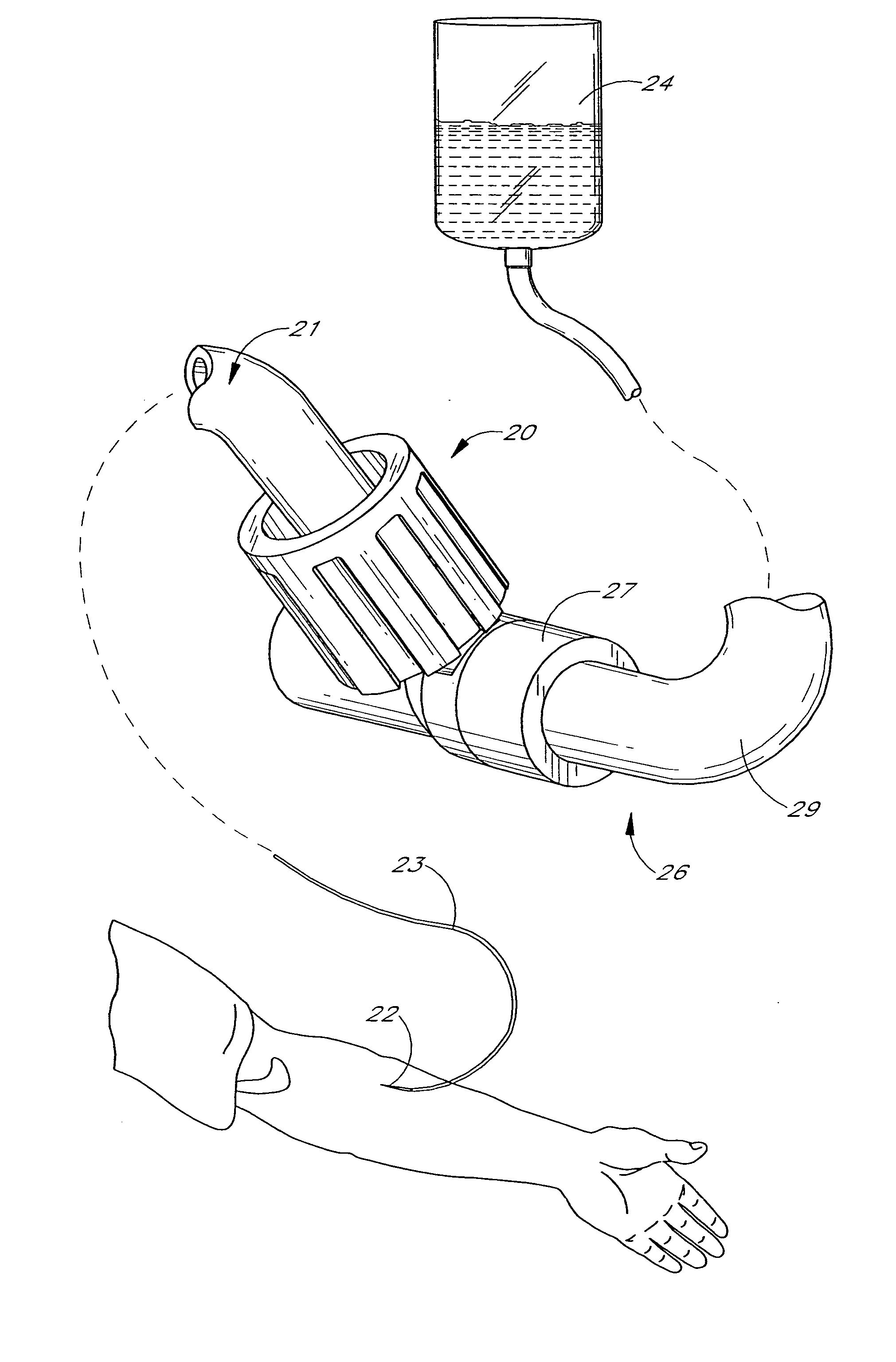
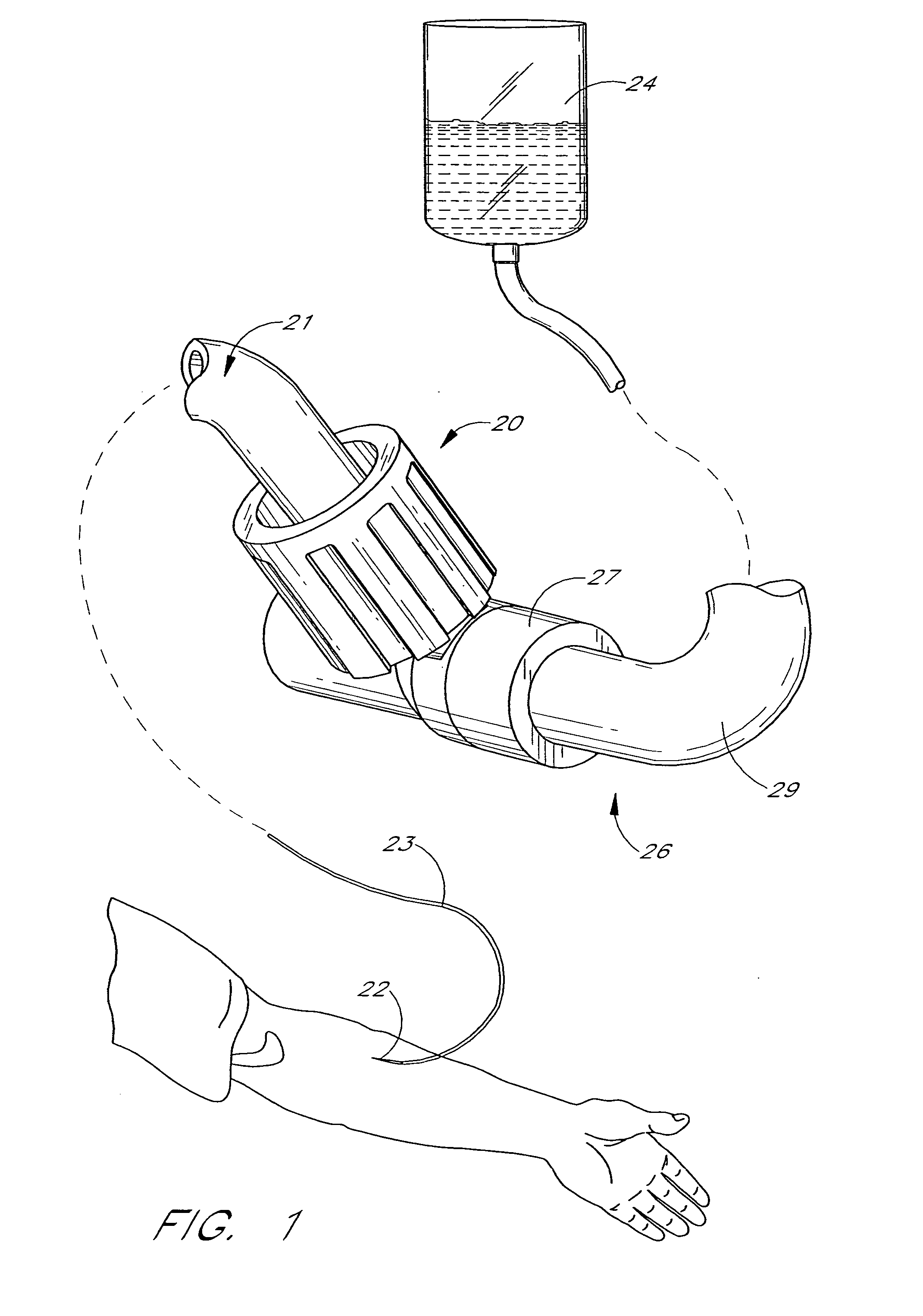
[0073]FIGS. 1-17 illustrate a valve 20 in accordance with a first embodiment of the present invention. FIG. 1 illustrates a particular use of the valve 20 to which the valve 20 is well suited. Of course, the valve 20 may be used in a variety of other manners.

[0074] As illustrated in FIG. 1, the valve 20 may advantageously be used to selectively control the flow of fluid to a catheter 22 from a fluid source 24 such as an I.V. bag. In this arrangement, a first medical implement 21 is connected to the valve 20. The first medical implement 21 comprises a tube 23 leading to a catheter 22. One end of the tube 23 is connected to the valve 20, and the catheter 22 has its tip positioned in a patient.

[0075] A second medical implement 26 is also connected to the valve 20. The second medical implement 26 comprises a connecting member 27 positioned at one end of a tube 29 which leads to the I.V. bag 24.

[0076] When so connected, the valve 20 permits fluid to flow from the I.V. bag 24 or other ...

Example

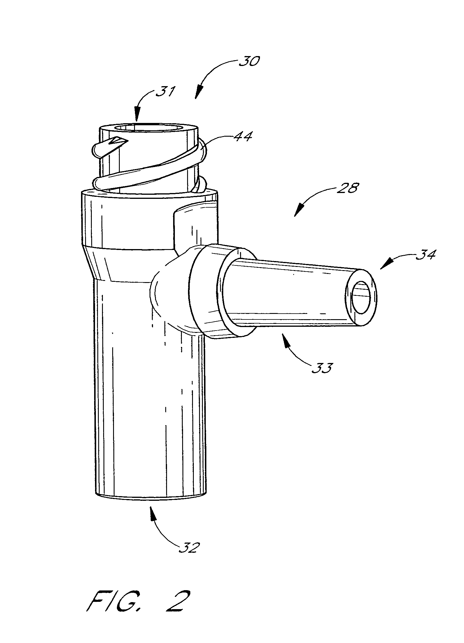
[0110] A second embodiment valve 120 in accordance with the present invention is illustrated in FIGS. 18 and 19. As illustrated, this valve 120 includes a housing 128 which is similar to the housing of the valve 20 described above, except that this housing is shorter in length between a first end 128 and a second end 130, as a piston 142 of the valve 120 is also shorter.

[0111] As illustrated, the first end 130 defines a first port 131, and the opposing second end 132 is closed. A branch 133 extends to a third end 134 defining a branch port 135.

[0112] A main passage 136 extends from the first end 130 towards the second end 132 of the housing. The main passage 136 is defined by an inner surface of a wall of the housing 128. The main passage 136 is generally cylindrical in shape, in this embodiment having no ledges or steps.

[0113] A branch passage 138 extends perpendicularly from the main passage 138 between the first and second ends 130,132 of the housing 128. The branch passage 13...

Example

[0131] A third embodiment valve 220 in accordance with the present invention is illustrated in FIGS. 20 and 21. As illustrated, this valve 220 includes a housing 228. As illustrated, the housing 228 is a generally cylindrical body having a first end 230 defining a first port 231 and having an opposing second end 232.

[0132] A main passage 236 extends from the first end 230 towards the second end 232 of the housing. The main passage 236 is defined by an inner surface of the housing 228. The main passage 236 is generally cylindrical in cross-section. An extension passage 238 of smaller diameter extends from the main passage 238 to the second end 232 of the valve 220, the passage 238 being defined partly by a wall 276. A sleeve 278 is positioned about the outside of the wall 276. The sleeve 278 preferably has threads 279 on an inner surface thereof.

[0133] The piston 242 is movably positioned within the passage 236 of the housing 228. The piston 242 has a body 260 having a generally ci...


PUM


Abstract

A medical valve device for use in selectively establishing a fluid flow between first and second medical implements is disclosed. The valve has a body defining a passage from a first port to a second port. The valve defines a first fluid volume when both medical implements are connected thereto, and a second, smaller volume when one of the implements is disconnected, thereby causing a positive flow of fluid from the valve to the second medical implement when the first implement is disconnected.

Description

RELATED APPLICATIONS [0001] This application is a continuation of U.S. patent application Ser. No. 09 / 879,364 filed Jun. 12, 2001, which is a continuation of U.S. patent application Ser. No. 09 / 078,941 filed May 14, 1998, which is a continuation-in-part of U.S. patent application Ser. No. 08 / 767,587 filed Dec. 16, 1996, all of which are incorporated by reference in their entirety.FIELD OF THE INVENTION [0002] This invention relates generally to a medical valve, and in particular to a valve which, when connected between a first medical implement, such as a fluid source, and a second medical implement, such as a catheter, facilitates fluid flow therebetween, and when the first medical implement is disconnected therefrom, induces a positive flow of fluid through the valve in the direction of the second medical implement. BACKGROUND OF THE INVENTION [0003] The manipulation of fluids for pareriteral administration in hospitals and medical settings routinely involves the use of connectors...

Claims


Application Information

Patent Timeline
IPC IPC(8): A61M25/00A61M5/168A61M39/00A61M39/04A61M39/26
CPCA61M39/045A61M39/26A61M2039/263A61M2039/266
Inventor FANGROW, THOMAS F. JR.SCHMIDT, JONATHAN T.WAIT, DANIEL J.BUI, DANNIS M.
Owner FANGROW THOMAS F JR
Why Eureka
Try Eureka