
Turbomachine with a long lasting position-holding system

a position-holding system and turbomachine technology, applied in the field of turbomachine, can solve the problems of wear and consumption of energy, limit on the maximum acceptable speed of rotation, friction and wear of ball bearings, etc., to minimize the consumption of fluid, optimize the overall energy efficiency of the turbomachine, and minimize the effect of the more penalized consumption of fluid

Active Publication Date: 2009-12-17
SN DETUDE & DE CONSTR DE MOTEURS DAVIATION S N E C M A
View PDF9 Cites 36 Cited by
  • Summary
  • Abstract
  • Description
  • Claims
  • Application Information

AI Technical Summary

Benefits of technology

[0019]A first object of the invention is to remedy the above-mentioned drawbacks by proposing a turbomachine arranged with a rotor and a stator, the turbomachine comprising: a fluid-flow portion enabling energy to be exchanged between a fluid passing therethrough and the rotor, including in particular at least one bladed wheel mounted on a shaft of the rotor; an electrical portion suitable for converting electricity into work or vice versa; radial positioning means serving to position the rotor radially; and a contactless axial balancing device arranged on said bladed wheel, providing axial balancing for the rotor at high speed; which turbomachine consumes little fluid and presents good volumetric efficiency, is relatively compact, has a long lifetime with little wear at the interfaces for holding the rotor in position, and is suitable for operation at high speeds.

Problems solved by technology

Nevertheless, ball bearings present the drawback of involving mechanical contact and thus friction between facing surfaces, thereby leading to wear and consuming energy, in particular at high speeds of rotation; they also put a limit on the maximum acceptable speed of rotation.
The drawback of that embodiment is that the inner ring of the ball bearing (secured to the rotor) and the balls are driven to rotate by the movement of the rotor, thereby giving rise to friction and wear in the ball bearing.
As a result, the lifetime of that portion of the electricity generator is limited.
That arrangement has the drawback of being complicated, and above all of lacking reliability.
In practice, since there can be no question of using a shaft of large diameter, the conicity of the bearing surface remains small, thereby giving rise to poor reliability during the declutching of the bearings and running the risk of strong interaction in operation between the ball bearings and the hydrostatic bearings.
In addition, having parallel radial holding means (ball bearings in parallel with hydrostatic bearings) leads to extra weight and to an increase in the volume of the machine.

Method used


Image

  • Turbomachine with a long lasting position-holding system
  • Turbomachine with a long lasting position-holding system
  • Turbomachine with a long lasting position-holding system

Examples


Embodiment Construction

[0048]When an element appears in more than one figure, it retains the same reference in the various figures, and it is described with reference to the first figure in which it appears.

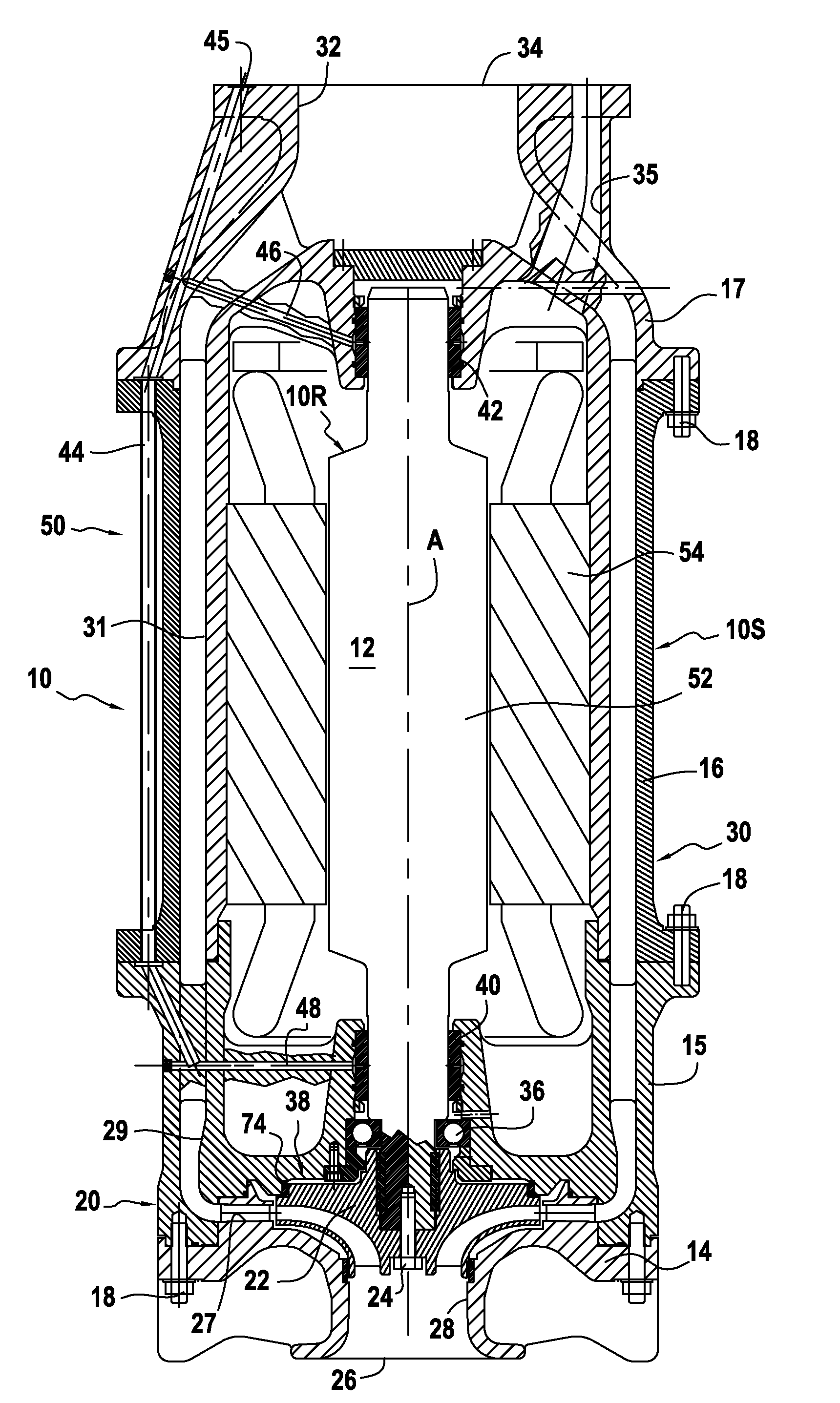
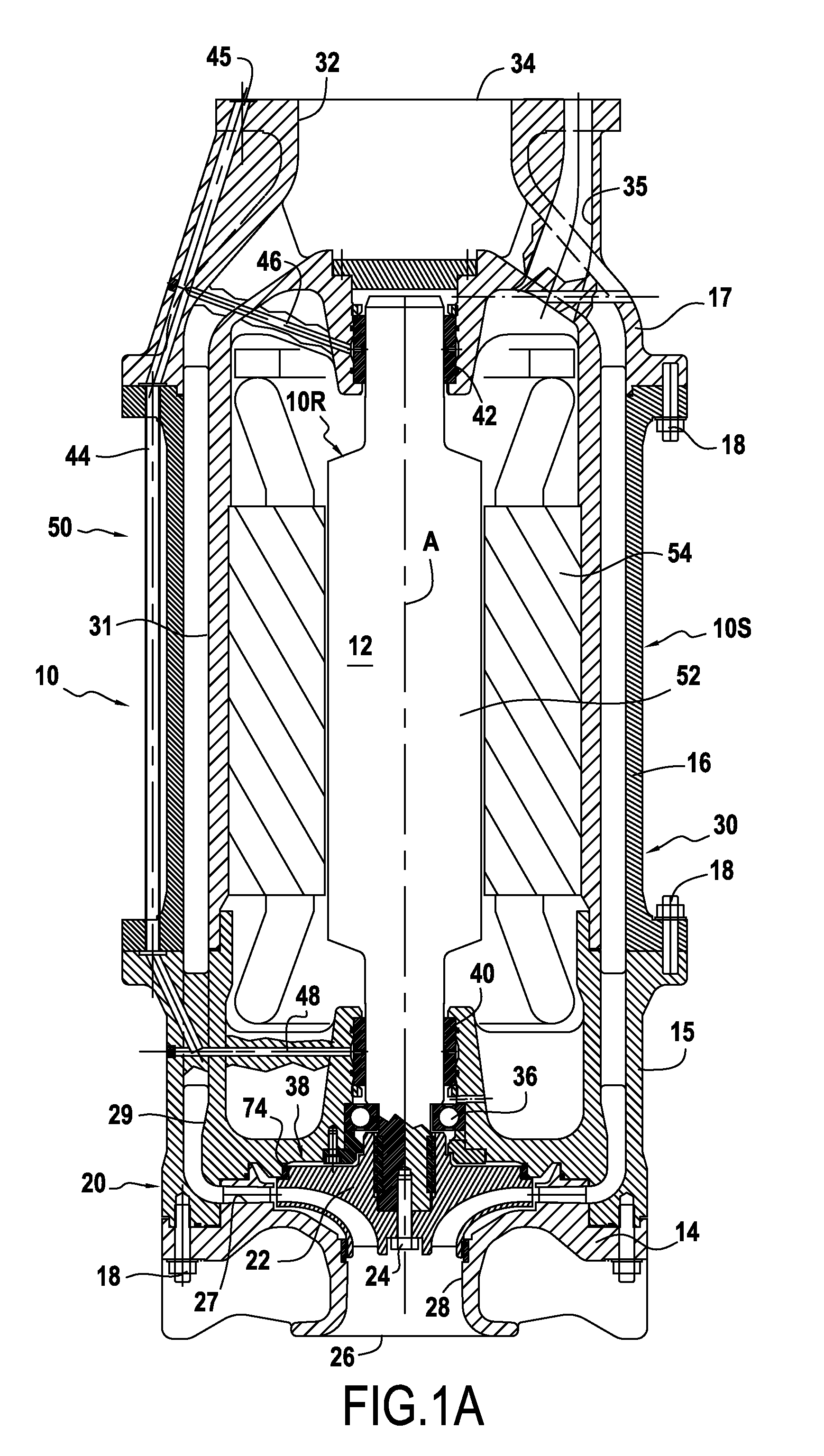
[0049]With reference to FIG. 1, a turbomachine of the invention is described below.

[0050]The turbomachine 10 is an electricity generator that is driven by a turbine. It comprises a fluid-flow portion 20, constituted by a turbine, and an electrical portion 50, constituting an electricity generator.

[0051]The turbomachine 10 is arranged in the form of a rotor 10R rotating about its shaft 12 in a stator 10S.

[0052]The stator 10S essentially comprises a casing 30 made of four portions 14, 15, 16, and 17. These portions are stationary and fastened to one another by screws 18. The stator also includes the stationary or stator portion 54 of the electricity generator.

[0053]The rotor 10R essentially comprises a bladed wheel 22 fastened to one end of the shaft 12 by a screw 24, by the rotor shaft 12 itself, and by...


PUM


Abstract

A turbomachine arranged with a rotor and a stator, including radial positioning means ensuring that the rotor is radially position; and a contactless axial balancing device arranged on at least one bladed wheel for axially balancing the rotor at high speed. The turbomachine includes a thrust bearing distinct from the radial positioning means serving to balance the rotor axially at low speed, and without contact at high speed. In addition, the radial positioning means are hydrostatic bearings, the turbomachine including hydrostatic bearing feed circuits suitable for connecting said bearings to a source of fluid under pressure. As a result, it is possible to obtain operation at high speeds with a very long lifetime.

Description

FIELD OF THE INVENTION[0001]The present invention relates to a turbomachine arranged with a rotor and a stator, and more particularly the invention relates to an improvement to its means for holding the rotor in position relative to the stator.[0002]The turbomachine comprises a fluid-flow portion and an electrical portion that co-operate to enable energy to be exchanged between a fluid flowing through the machine and an electrical circuit.[0003]This exchange may take place in either direction: thus, such a turbomachine may be a compressor, having an electric motor as its electrical portion that drives a fluid-flow portion such as a pump; it may also be an electricity generator, the fluid-flow portion being a turbine that drives the electrical portion, which then constitutes an electricity generator, e.g. an alternator.BACKGROUND OF THE INVENTION[0004]This type of turbomachine is used in particular in the form of an expansion turbine or a high pressure pump in the liquefied natural g...

Claims


Application Information

Patent Timeline
IPC IPC(8): F01D3/00F01D15/10F01D25/16
CPCF03B11/06F03B11/063F03B13/10F04D29/042F04D29/052F16C2360/23Y02E10/22Y02E10/223Y02E10/226F16C21/00F16C32/064F05B2240/53F16C39/02F16C2360/00F16C2380/26Y02E10/20F01D5/02F01D25/16F03B13/00
Inventor BEGIN, VALERIEBOUDEHEN, FREDERICDANGUY, FRANCOISFROCOT, MANUEL
Owner SN DETUDE & DE CONSTR DE MOTEURS DAVIATION S N E C M A
Learn More