Electrical generator with separated coil and set of magnets

a technology of electric generators and coils, applied in the direction of magnetic circuit rotating parts, magnetic circuit shapes/forms/construction, cycle equipment, etc., can solve the problems of high manufacturing cost, and difficult assembly of rotors and stators

Inactive Publication Date: 2004-06-29
FU MING HUA +1
View PDF4 Cites 54 Cited by
  • Summary
  • Abstract
  • Description
  • Claims
  • Application Information

AI Technical Summary

Problems solved by technology

1. Proper alignment of the rotor and the stator is critical, which may make assembly difficult.
The assembly of the rotor and the stator is made more difficult because two bearings are required to carry the

Method used


Image

  • Electrical generator with separated coil and set of magnets
  • Electrical generator with separated coil and set of magnets
  • Electrical generator with separated coil and set of magnets

Examples


Embodiment Construction

Faraday's Law states that a changing magnetic field will induce a voltage in a coil of conductive wire. More specially, Faraday's Law states that a time-varying flux induces an electromotive force (emf) in the coil.

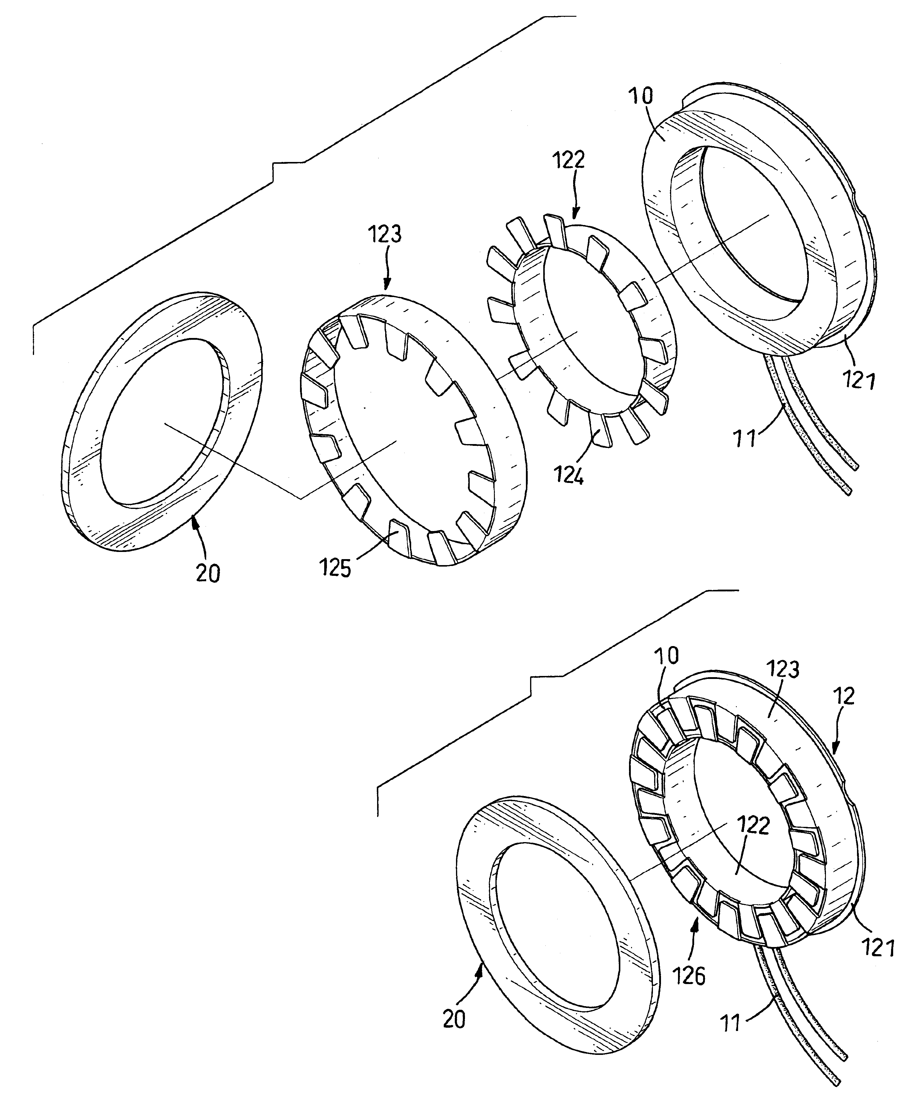
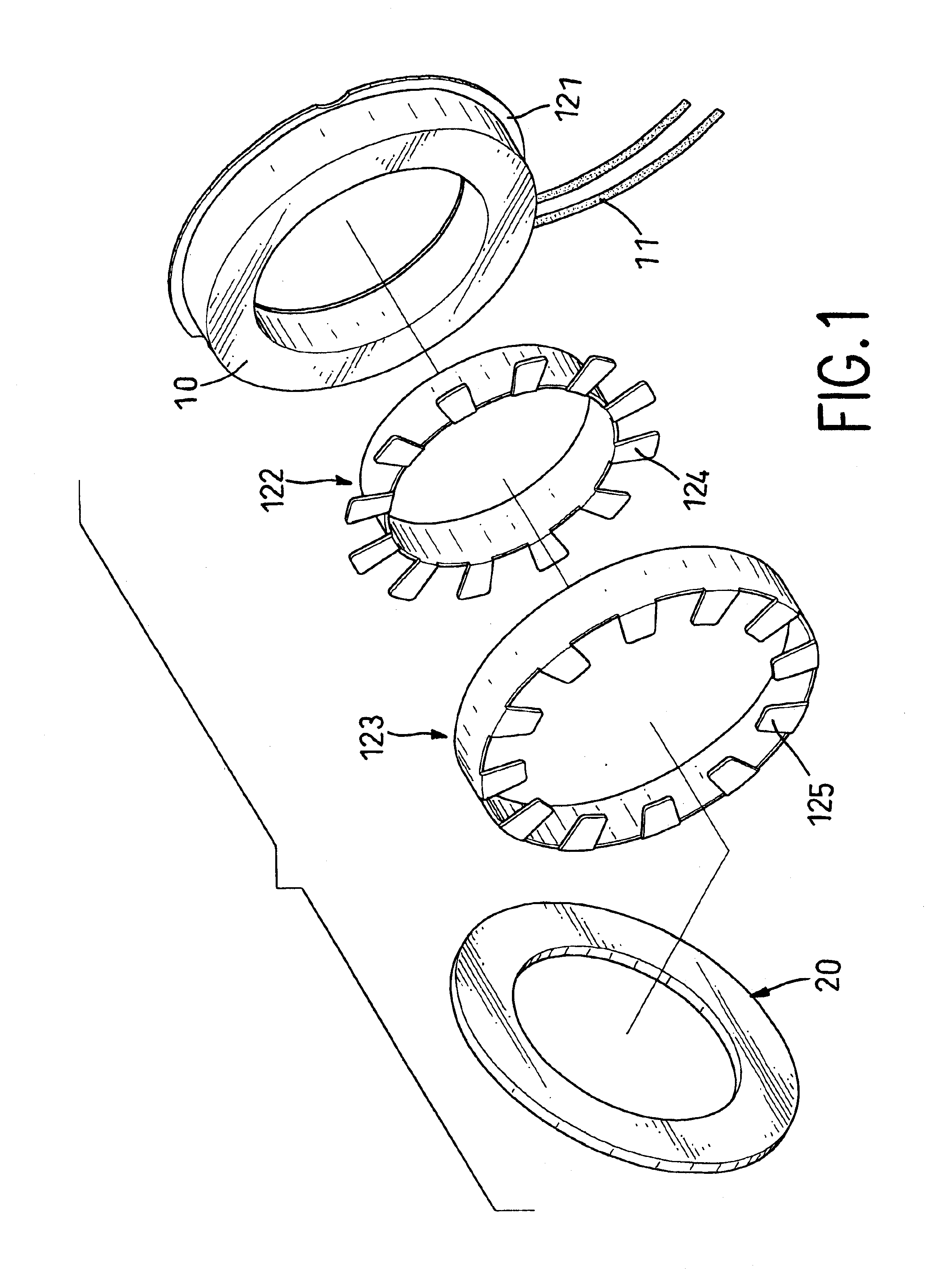
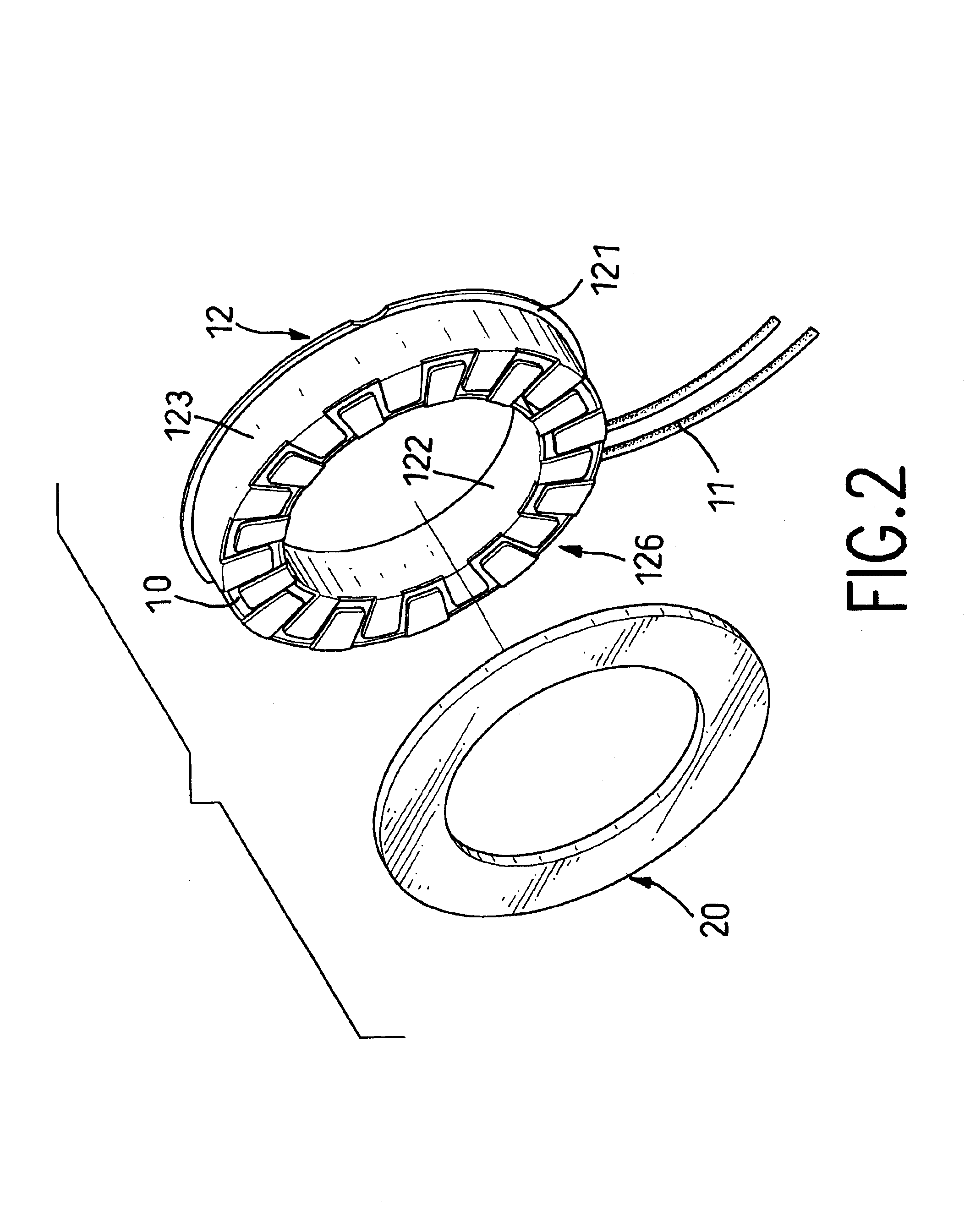
With reference to FIGS. 1 and 2, an electrical generator in accordance with the present invention comprises a coil (10), a coil seat (12) and a set of permanent magnets (20). An electrically conductive wire (not numbered) is wound in a ring shape to form the coil (10). The coil (10) has a first side (not numbered), a second side (not numbered) and two connecting wires (11). The connecting wires (11) are electrically connected respectively to opposite ends of the conductive wire forming the coil (10) and extend out of the coil seat (12).

The coil (10) is mounted in the coil seat (12). The coil seat (12) includes a base (121), an inside sidewall (122) and an outside sidewall (123). The inside sidewall (122) and the outside sidewall (123) respectively have an inner edge (not ...


PUM


Abstract

An electrical generator includes a coil, a coil seat and a set of permanent magnets. The coil and the set of permanent magnets are separated from each other. The coil is mounted in the coil seat so that either the coil or the set of permanent magnets can rotate relative to the other. The set of permanent magnets has multiple north poles and south poles arranged alternately. The set of permanent magnets is adjustably positioned relative to the coil seat. The set of permanent magnets is maintained a distance from the coil seat and induces a voltage in the coil in the coil seat when the set of permanent magnets rotates relative to the coil.

Description

1. Field of the InventionThe present invention relates to an electrical generator, and more particularly to an electrical generator with a coil and a set of magnets that are separated from each other.2. Description of Related ArtElectrical generators convert mechanical energy to electricity. A conventional generator includes a stator and a rotor. The stator has a frame and a winding. The frame has an inner space defined longitudinally and the winding is mounted in the frame around the inner space. The winding is made of conductive wire so the winding will conduct a current.The rotor includes a set of permanent magnets and an armature. The set of permanent magnets has north and south poles alternately mounted circumferentially on the armature. When the generator is assembled, the armature is rotatably mounted in the inner space in the stator, and the set of permanent magnets is positioned corresponding to the winding. A gap exists between the set of permanent magnets and the winding....

Claims


Application Information

Patent Timeline
IPC IPC(8): H02K1/14H02K7/18H02K21/12H02K21/14H02K21/24
CPCH02K1/145H02K7/183H02K7/1846H02K21/145H02K21/24Y02E10/725Y02E10/72
Inventor CHIU, CHUN-CHEN
Owner FU MING HUA
Why Eureka
Try Eureka