

Disc clamping device
a technology of clamping device and disc, which is applied in the field of disc clamping device, can solve the problems of unsatisfactory performance, thicker clamping device, and the inability to lower the height of the device,
- Summary
- Abstract
- Description
- Claims
- Application Information
AI Technical Summary
Benefits of technology
Problems solved by technology
Method used
Image

Examples
Embodiment Construction
Embodiments of the present invention are described as follows. A spindle motor is used as a device to drive various media discs such as CD-ROMs.
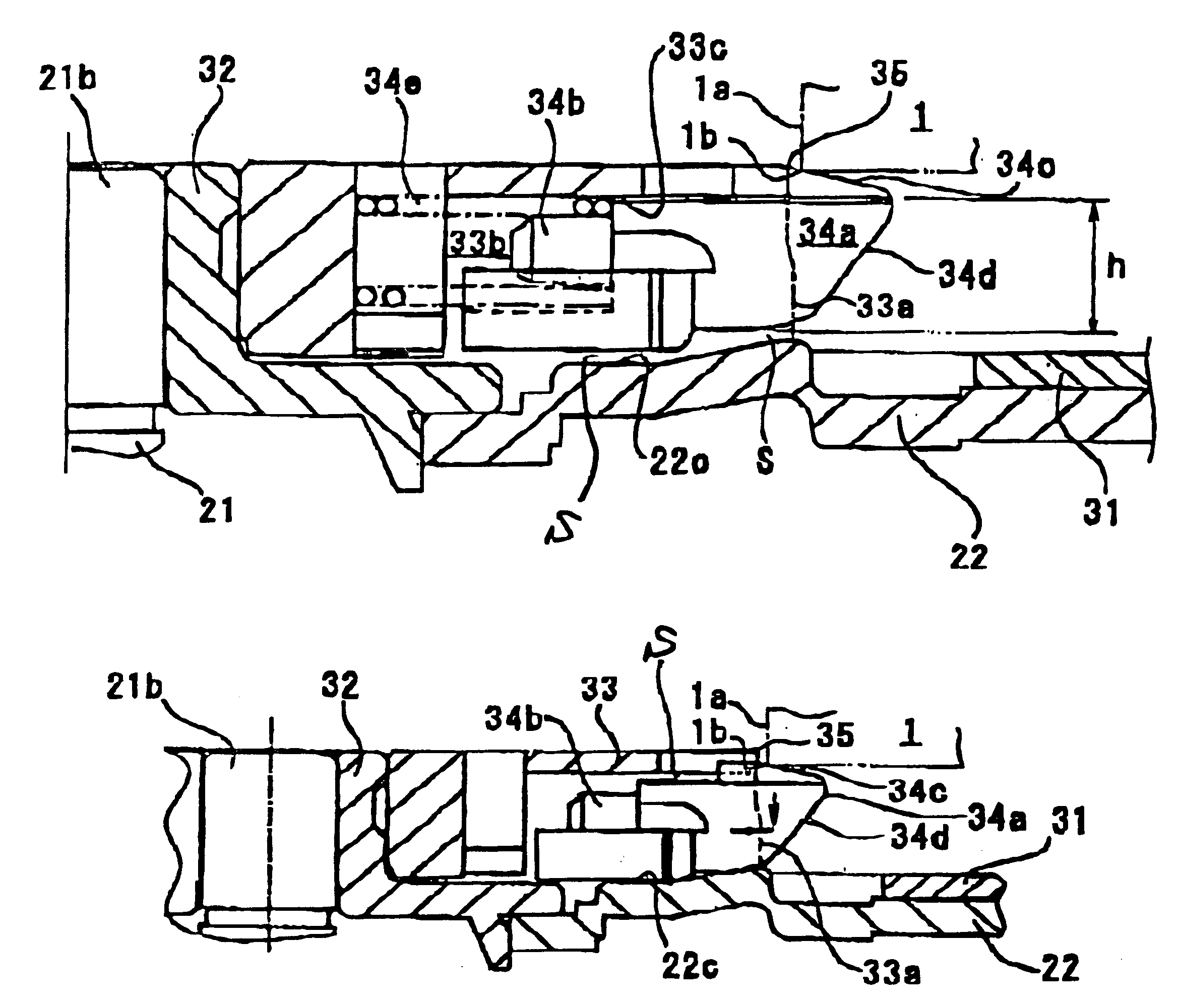
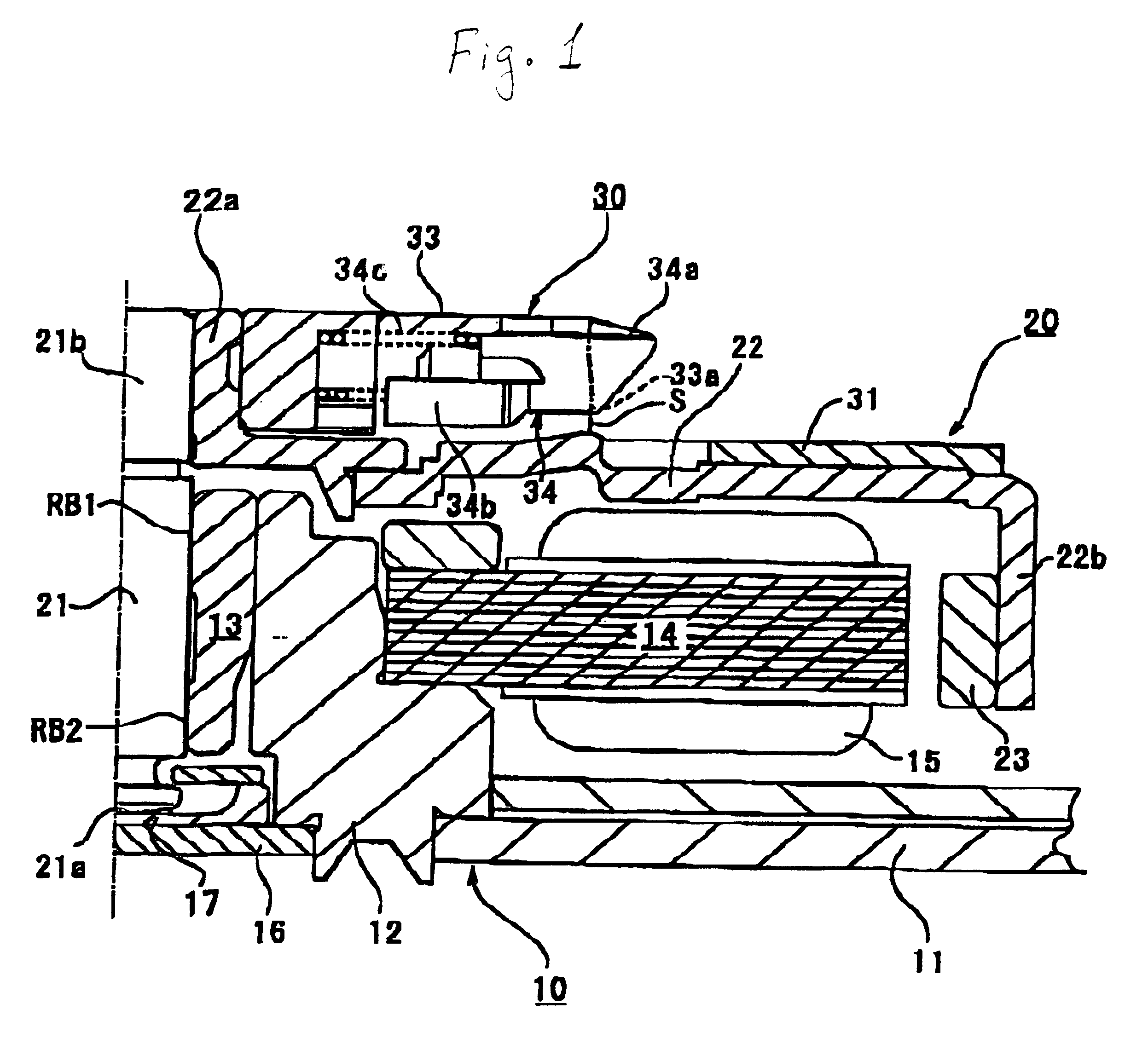
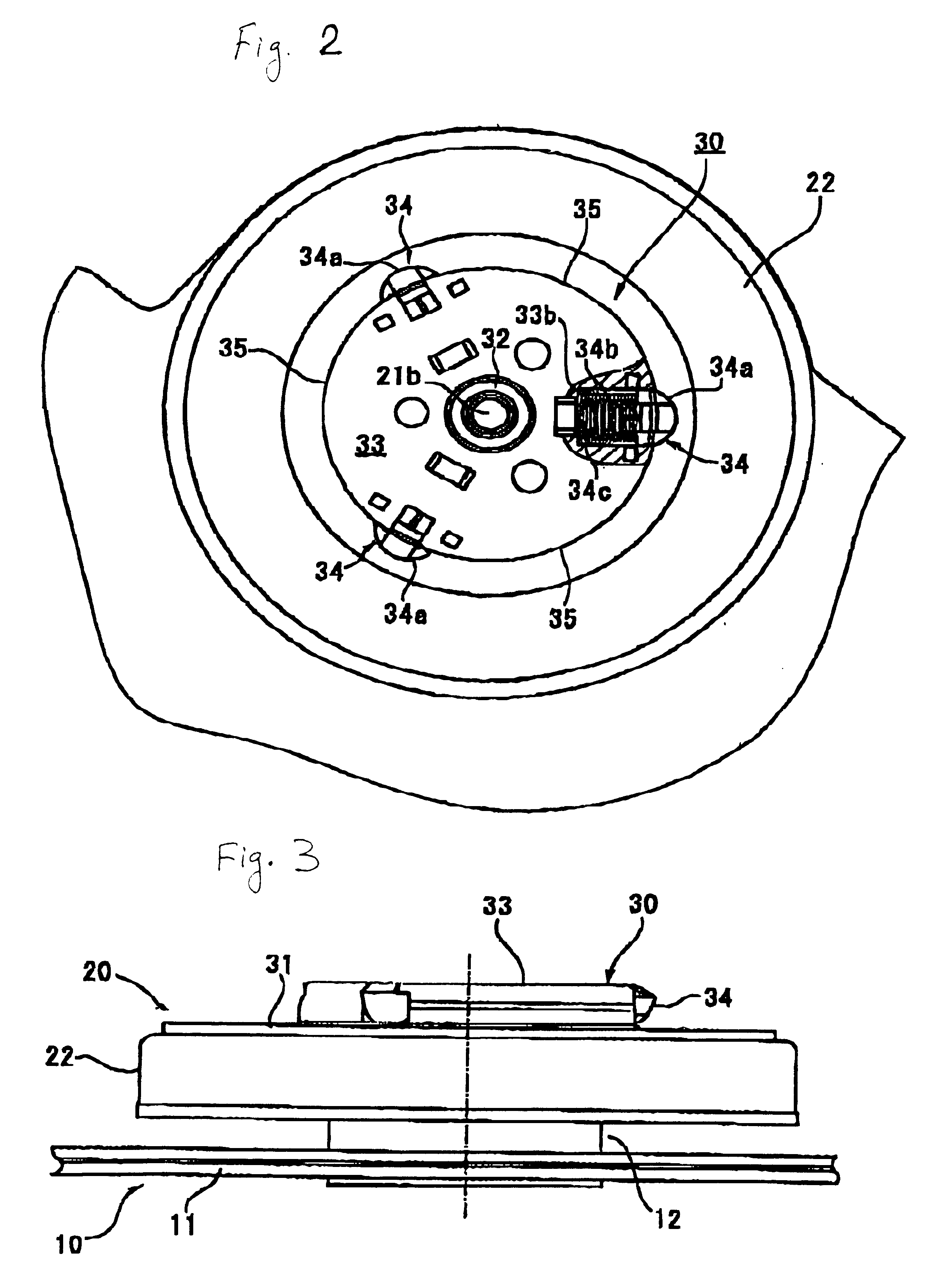
The entire spindle motor for a disk driving apparatus of a shaft rotating type shown in FIG. 1, FIG. 2 and FIG. 3 includes a stator assembly 10 as a fixed member and a rotor assembly 20 being a rotatory member which is assembled to the stator assembly 10 in an axial direction.
The stator assembly 10 includes a bearing holder 12 fixed at a generally center area of a fixed plate (base plate) 11 and a generally hollow cylinder-shaped bearing sleeve 13 inserted into the inside of the bearing holder 12. The bearing sleeve 13 is formed from a metal bearing member or a dynamic pressure bearing member and is fixed by an adhesive material (not shown). This bearing sleeve 13 may be joined with the bearing holder 12 by means of press fitting or shrinkage fitting.
The bearing holder 12 is provided with a mounting stop portion formed by an outer peripheral...
PUM
| Property | Measurement | Unit |
|---|---|---|
| angle | aaaaa | aaaaa |
| fringe angle | aaaaa | aaaaa |
| force | aaaaa | aaaaa |
Abstract
Description
Claims
Application Information