
Method and apparatus for quenching the coke drum vapor line in a coker

a technology of vapor line and coke drum, which is applied in the direction of lighting and heating apparatus, separation processes, instruments, etc., can solve the problems of reducing yield, expensive event, and reducing unit feed ra

Inactive Publication Date: 2004-07-06
MOTIVA ENTERPRISES
View PDF15 Cites 19 Cited by
  • Summary
  • Abstract
  • Description
  • Claims
  • Application Information

AI Technical Summary

Problems solved by technology

Prior systems result in either of two undesirable conditions: (1) overquench, which reduces yields and possibly reduces unit feed rates, OR (2) underquench, which leaves a vapor line without any liquid to flush the line out into the main fractionator and which will eventually shut down the coker as the vapor line cokes.
Once the line cokes to the point of causing enough pressure drop from the coke drums to the main fractionator such that all the liquid evaporates, only a short time remains until the coker must be shut down--a very expensive event.
In the prior systems, the quench cannot generally be adjusted to target its contribution to the recycle ratio.
The problem with putting a TI in this location is that, in all likelihood, it will foul and become inaccurate.
Prior quench techniques do not consider pressure differential between the coke drum and the fractionator.
Plugging of the vapor line causes a restriction in coker unit feed rates and ultimately leads to severely limiting coker feed rates until the plug is removed.
In order to remove the vapor line plug, shut down of the unit is required which results in lost coker capacity, due to the gradual slowdown and subsequent shutdown of the coker unit, and in significant economic loss.

Method used


Image

  • Method and apparatus for quenching the coke drum vapor line in a coker
  • Method and apparatus for quenching the coke drum vapor line in a coker
  • Method and apparatus for quenching the coke drum vapor line in a coker

Examples


Embodiment Construction

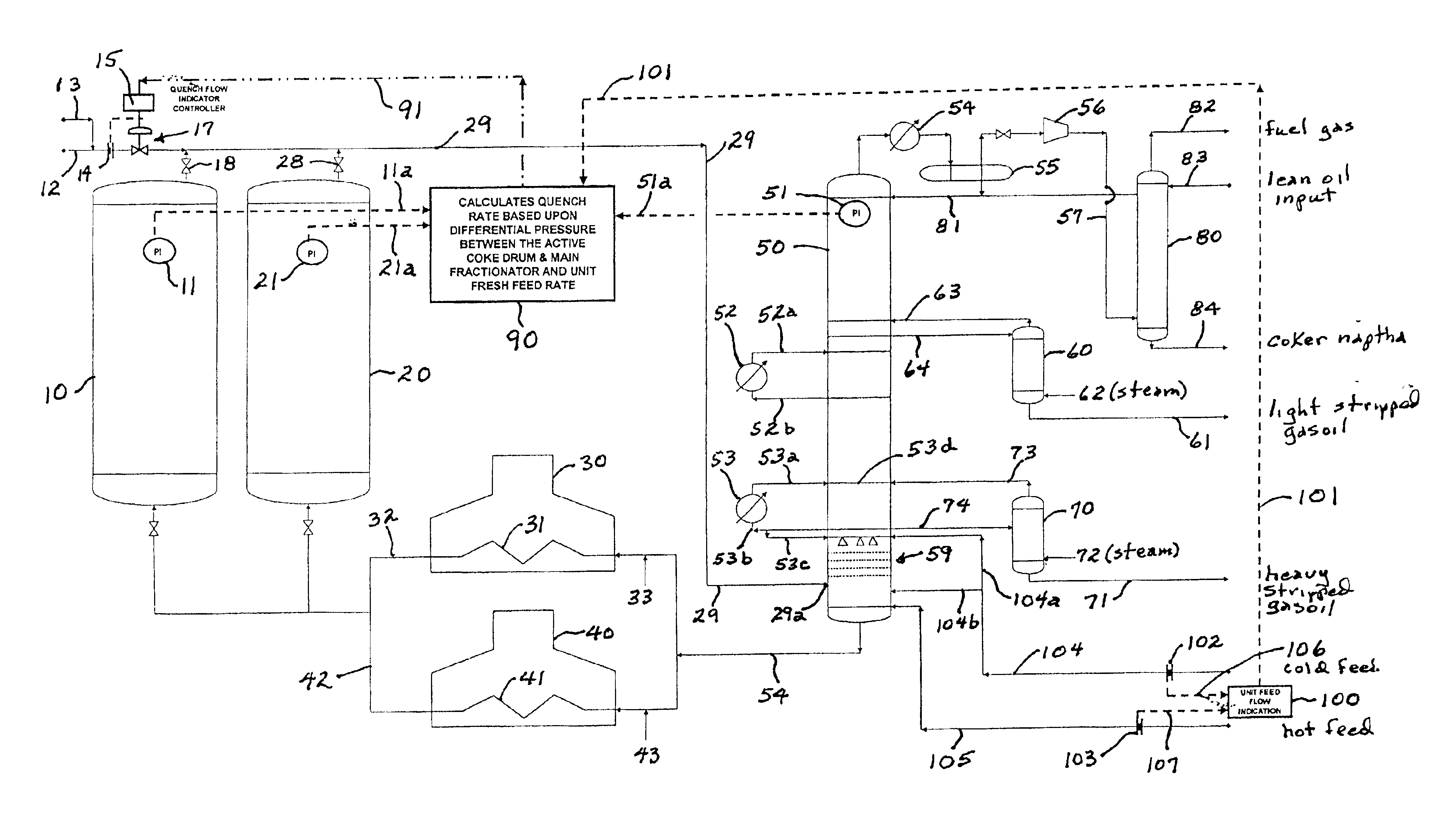
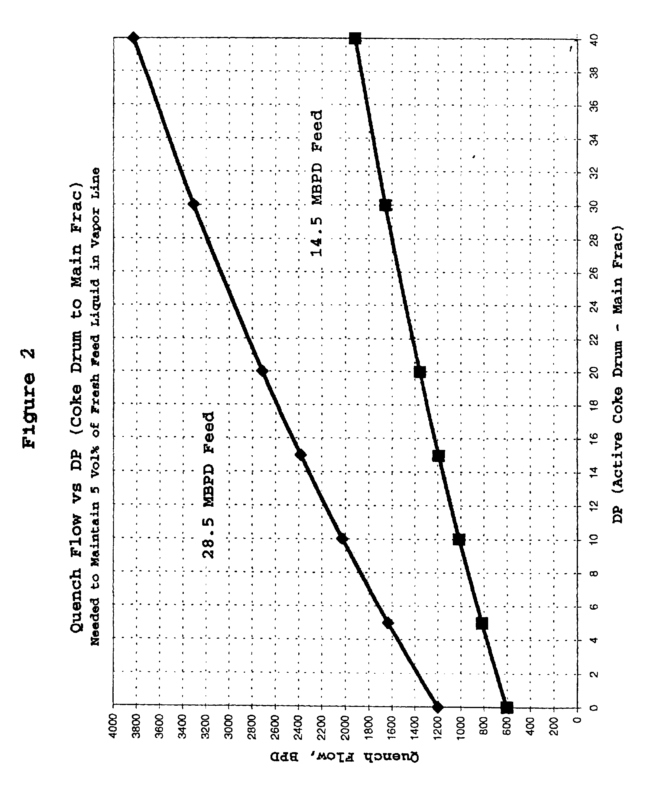
The root cause of a coker vapor line plug is drying out of the vapor line. In particular, during coke drum warm-up, the vapor line may dry out due to the increased pressure drop from the coke drum to the fractionator if there is no increase in quench rate to prevent drying. This added pressure drop can cause all of the liquid to flash off inside the vapor line which leaves a layer of carbon residue with entrained coke fines. To reduce the risk of plugging the vapor line, the quench technique disclosed herein adjusts quench rates based upon pressure drop and unit feed rate. This delta pressure quench control technique greatly reduces the potential of the vapor line drying out and maintains a constant flow of liquid flowing out the end of the vapor line into the fractionator. It will generally increase yields vis-a-vis the prior art delta temperature quench control (if the vapor line temperature indicator (TI) is not located near the fractionator), or the constant vapor temperature qu...


PUM

PropertyMeasurementUnit
Temperatureaaaaaaaaaa
Pressureaaaaaaaaaa
Flow rateaaaaaaaaaa

Abstract

A method and apparatus for quenching the coke drum vapor line from a coke drum to the main fractionator in a coker unit whereby the volume of quench liquid prevents the drum vapor line from plugging with carbon-based deposits. A differential pressure control technique is utilized to quench the drum vapors being delivered to the fractionator as opposed to a temperature, delta temperature, uninsulated vapor line, or fixed flow rate control as used in the prior art. Vapor line quench control by differential pressure prevents over-quenching of the vapor line during a coke drum switch, unit startup, or slowdown as well as under-quenching during drum warm-ups. It improves the fractionator recovery time from a drum switch and overall liquid product yield during the drum cycle which can be produced by over-quenching. It also prevents the vapor line from drying out at anytime, an under-quenched condition, as long as the quench oil quality and conditions do not vary significantly.

Description

1. Field of the InventionThe invention is related to coker units and their operation, particularly in the quenching of the vapor line running from coke drums to a fractionator in a coker unit.2. Description of Related ArtFlow rate in a coke drum vapor line is influenced by several factors including quench injection rate, quench oil properties, coke drum temperature, vapor rate and pressure drop from the coke drums to the fractionator. In prior systems, the actual rate of liquid flowing out of the vapor line into the coker main fractionator varies during the coking cycle and can go to zero liquid flow, a dry vapor line condition which can eventually lead to plugging of the vapor line. Prior systems result in either of two undesirable conditions: (1) overquench, which reduces yields and possibly reduces unit feed rates, OR (2) underquench, which leaves a vapor line without any liquid to flush the line out into the main fractionator and which will eventually shut down the coker as the ...

Claims


Application Information

Patent Timeline
IPC IPC(8): C10G9/00C10B55/00C10B41/00C10B57/04
CPCC10B55/00C10G9/005Y10S208/01
Inventor HAIK, STEPHEN MICHEL
Owner MOTIVA ENTERPRISES
Learn More