Laminated balun transformer

a balun transformer and laminate technology, applied in the direction of inductance, one-port network, waveguide type devices, etc., can solve the problems of inability to apply a bias voltage to only the balanced transmission line, and the inability to amplify the balanced signal

Inactive Publication Date: 2004-07-27
MURATA MFG CO LTD
View PDF11 Cites 30 Cited by
  • Summary
  • Abstract
  • Description
  • Claims
  • Application Information

AI Technical Summary

Problems solved by technology

Thus, it is impossible to apply a bias voltage to only the balanced transmission lines.
In other words, the

Method used


Image

  • Laminated balun transformer
  • Laminated balun transformer
  • Laminated balun transformer

Examples


Embodiment Construction

The laminated balun transformer of the present invention is not limited to the above-described preferred embodiments, and thus can be changed within the sprit and scope of the present invention.

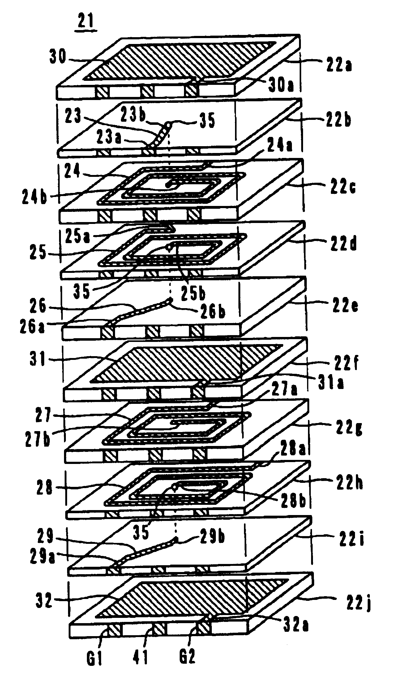
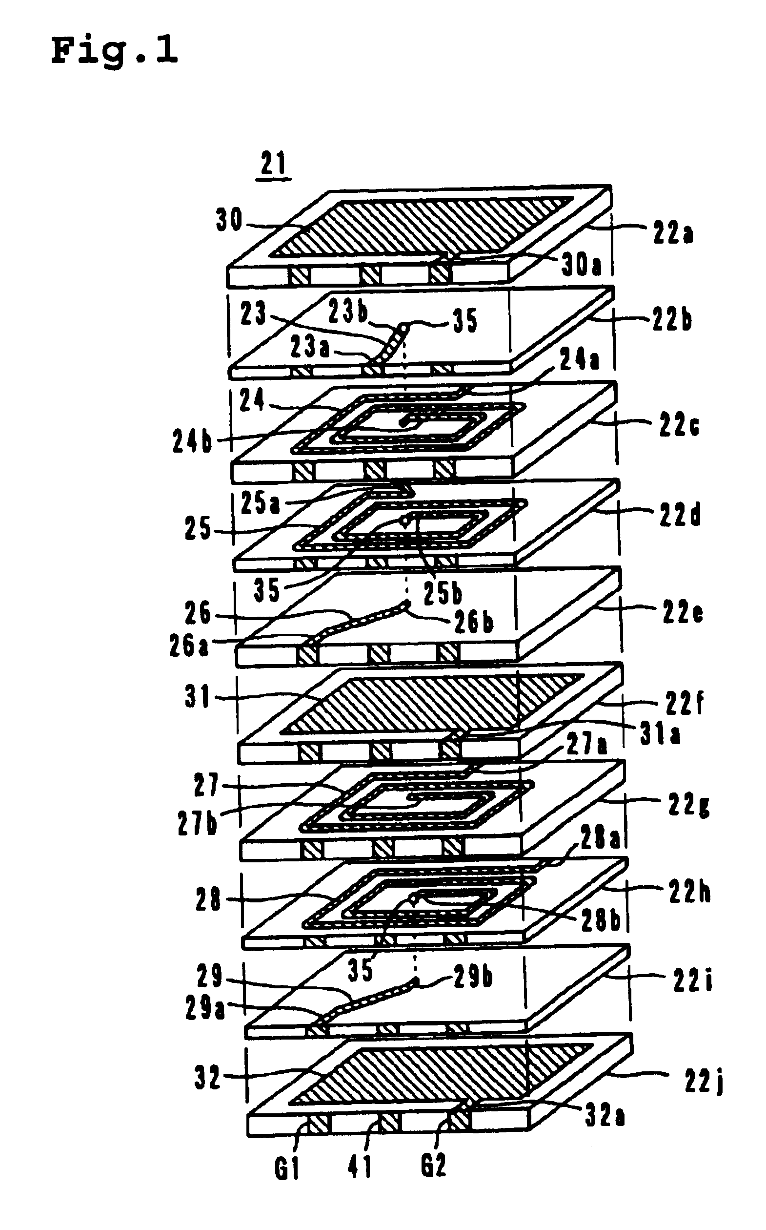
For example, the line elements 24, 25, 27, 28 may have any shape, and thus may have a spiral, curved, or straight shape, or other suitable shape. In addition, the line elements do not necessary have to be set to a length of 1 / 4 wavelength, and also the line widths of all the line elements also do not have to be the same.

Additionally, the structure of the line elements is not limited to the strip line structure arranged between two shield electrodes, and may be a so-called "microstrip line structure" in which line elements are arranged on the obverse surface of a dielectric substrate (on the reverse surface, a shield electrode is provided).

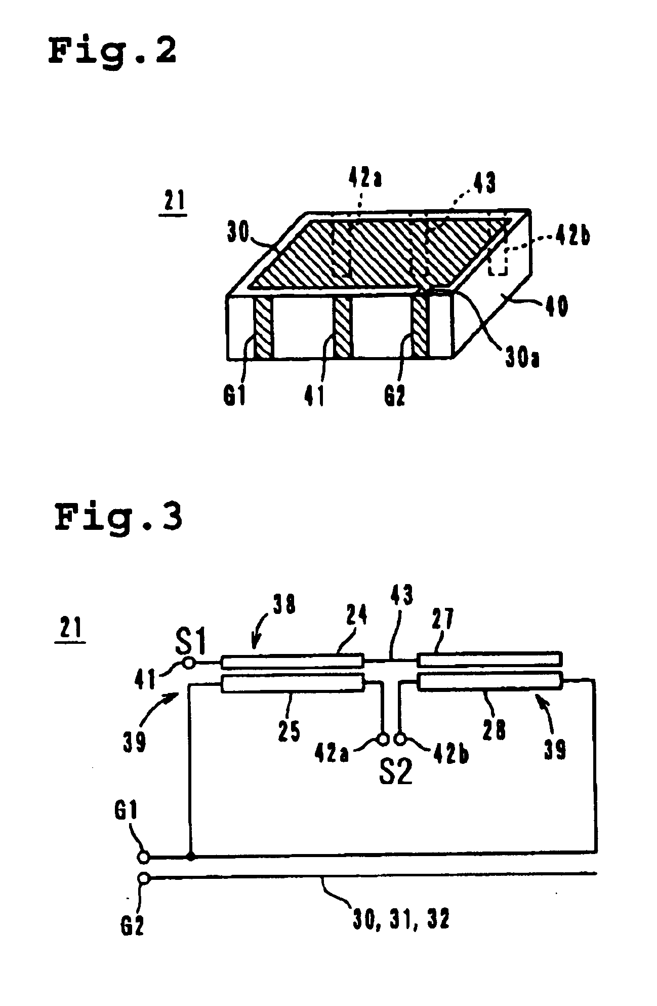
In the laminated balun transformers of various preferred embodiments described above, the coupler constituted by the line elements 24 and 25 and the coupler...


PUM


Abstract

A laminated balun transformer includes first line elements which are connected in series through a relay terminal, to constitute an unbalanced transmission line. Other line elements each constitute a balanced transmission lines. Strip lines are electromagnetically coupled to constitute a coupler. Similarly, other line elements are electromagnetically coupled to constitute a coupler. A ground terminal is connected to the balanced transmission lines, which are constituted by a pair of the line elements. Meanwhile, a shield terminal is connected to leading portions of shield electrodes. These two terminals are electrically independent of each other.

Description

1. Field of the InventionThe present invention relates to laminated balun transformers, and more particularly, to a laminated balun transformer for use as a balanced-to-unbalanced signal converter, a phase transformer, or other suitable device for an IC for a radio communication apparatus.2. Description of the Related ArtA balun transformer is used to convert, for example, a balanced signal from a balanced transmission line into an unbalanced signal for an unbalanced transmission line or to convert an unbalanced signal from an unbalanced transmission line into a balanced signal for a balanced transmission line. The term "balun" is an abbreviation of "BALanced-UNbalanced".A balanced transmission line has a pair of signal lines, through which a signal (a balanced signal) propagates as a potential difference therebetween. In a balanced transmission line, the two signal lines are equally affected by external noise, thereby canceling out the external noise. Thus, the balanced transmissio...

Claims


Application Information

Patent Timeline
IPC IPC(8): H01F17/00H03H7/00H01P5/10H03H7/42H01F19/06
CPCH01F17/0013H01P5/10H03H7/422H01F27/2804H01F2017/008H01F17/00
Inventor YAZAKI, HIROKAZUTOUJO, ATSUSHI
Owner MURATA MFG CO LTD
Why Eureka
Try Eureka