Dual elevation weapon station and method of use

a weapon station and dual-altitude technology, applied in the direction of weapons, aiming means, sighting devices, etc., can solve the problems of user completely losing the view of the target in the sight, the sighting or aiming system no longer views the target, and the gun sight and the weapon share a common elevation mechanism

Inactive Publication Date: 2004-08-03
EOS DEFENSE SYST
View PDF8 Cites 49 Cited by
  • Summary
  • Abstract
  • Description
  • Claims
  • Application Information

AI Technical Summary

Benefits of technology

Another object of my invention is to provide a GWS that eliminates the need for an offset mechanism when super-elevation is needed for correct ballistic trajectory. This is accomplished by providing full elevation axes for both the weapon cradle and sighting device.
A further object is to provide a GWS where the dual elevation axes are stabilized independently or in common. Stabilization is very beneficial when large mass weapons are used with my GWS or when the GWS is used on a moving platform, such as a tank, troop carrier or other wheeled vehicle or boat deck.
Yet another object of my invention is to provide a control algorithm to coordinate the movement of the two independent elevation axes so that the user can continuously view and track a target without interruption and which will allow the weapon cradle (and the installed weapon) to achieve a correct super-elevation position independent of the actual elevation of the sighting device.

Problems solved by technology

Such systems, however, suffer from the drawback that both the gun sight and the weapon share a common elevation mechanism.
However, in situations referred to as super-elevation, where the weapon must be elevated to a greater angle than the target line of sight in order to launch the projectile to the hit the target over a long distance, the sighting or aiming system no longer views the target since the aim point of the gun no longer includes the target in the field of view.
In situations where a fire control computer can correct for ballistic trajectory (i.e., it can automatically raise the weapon to a super-elevation position to ensure the projectile impacts the target) a serious problem arises when there is only one elevation axis.
This causes the user to completely lose view of the target in the sight.
The disadvantage of this system is that it can introduce errors in the aiming accuracy because of the added complexity and mass of the additional counter rotation system components, which are placed on the single weapon elevation axis.
This added complexity and mass must be added to the sole elevation mechanism, which greatly increases the chances for error in aiming the gun during super elevation.
Another disadvantage is that counter rotation has a very limited range of movement and it can also introduce target image blur as the offset between the gun and sight is being established.
In each of these known offset systems, however, the amount of offset possible is very limited, which of course drastically limits target range capability.

Method used


Image

  • Dual elevation weapon station and method of use
  • Dual elevation weapon station and method of use
  • Dual elevation weapon station and method of use

Examples


Embodiment Construction

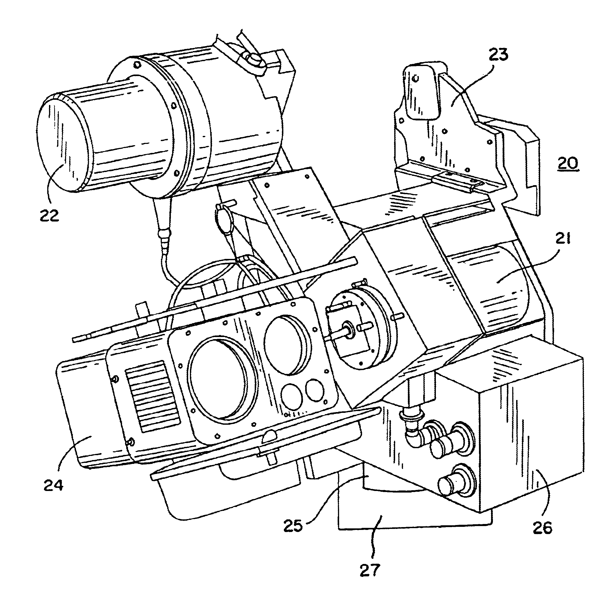
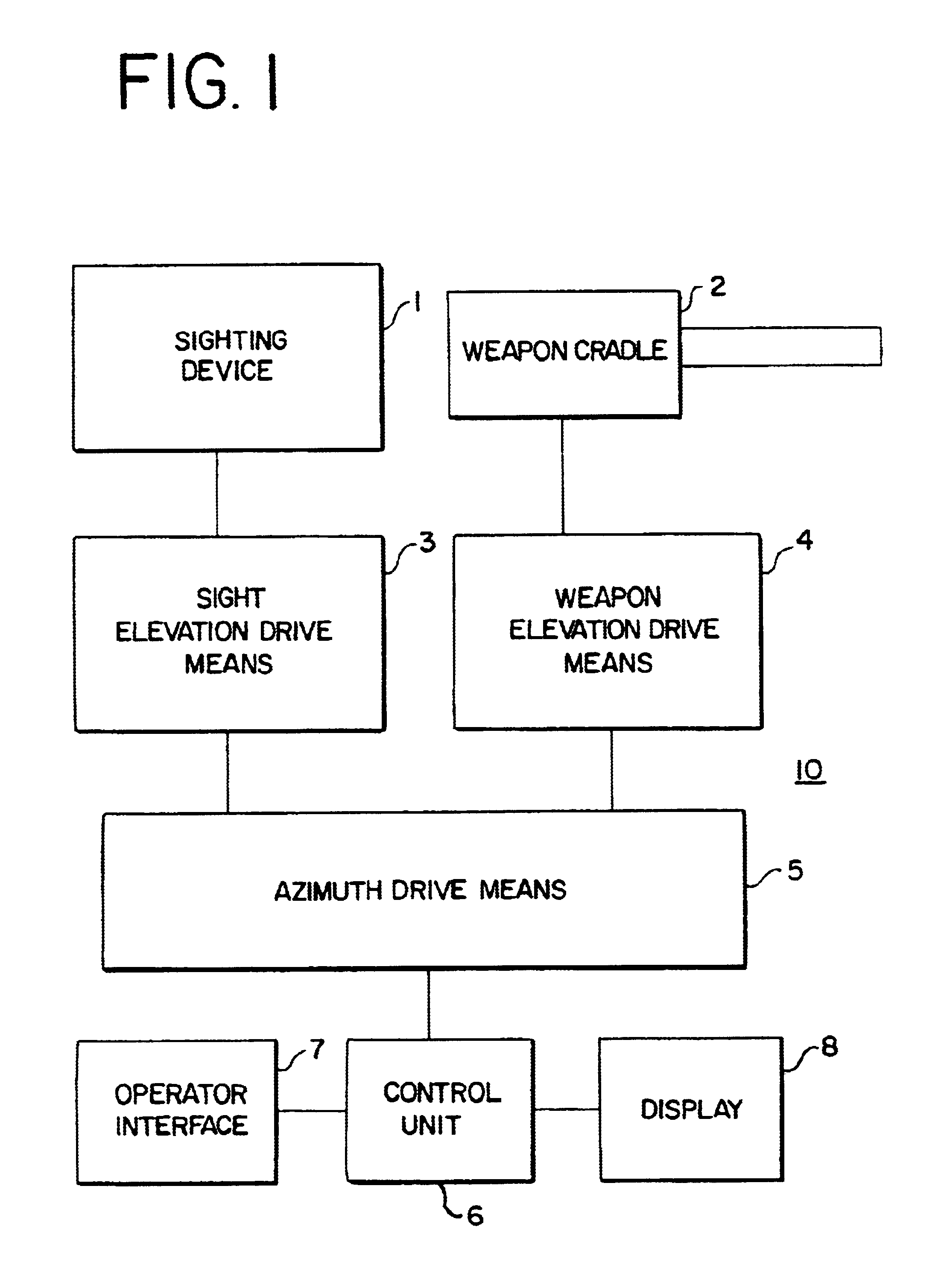
My invention is directed to a self-contained gimbaled weapon system (GWS) that has a sighting device and a weapon cradle where each has its own independent elevation axis. The GWS moves 360.degree. in azimuth and allows the sighting device and weapon cradle to each move in elevation independently of each other, thereby allowing a weapon operator to always maintain visual contact with a target through the sighting device, yet allows the weapon cradle to achieve super-elevation positions to accommodate correct ballistic trajectories. FIG. 1 is a block diagram of my invention showing GWS 10 comprising sighting device 1 connected to a first sighting elevation means 3, which is detachably connected to azimuth drive means 5. Weapon cradle 2 is connected to a second elevation means 4, which, like first elevation means 3, is connected to azimuth drive means 5. Control of both elevation means 3 and 4 and azimuth drive means 5 is accomplished with control unit 6. Control unit 6 is connected t...


PUM


Abstract

A self-contained gimbaled weapon system (GWS) has a shared azimuth axis and two independent elevation axes for a sighting device and a weapon cradle. The GWS allows the weapon cradle to be elevated completely independent of the sighting device. The GWS can be stabilized and operated remotely.

Description

1. Field of InventionMy invention relates generally to gimbaled weapon stations (GWS) that provide sighting, fire control and a weapon cradle in a self-contained system and to methods for using a GWS. In particular, the gimbaled weapon station of my invention allows a weapon cradle and a sighting device to move together in azimuth, but each can be elevated completely independently of each other. This allows for continuous target tracking and sighting regardless of the super-elevation needed for the weapon to achieve the correct ballistic trajectory. My weapon station can also be stabilized and operated remotely.2. Description of the Prior ArtTarget tracking and weapon control systems are known. For example, on ships, a single weapon sight that can move in both azimuth and elevation can control and direct fire of several large weapons. These large weapons can also move in both azimuth and elevation in response to signals received from a fire control computer, which receives input fro...

Claims


Application Information

Patent Timeline
Patent Type & Authority Patents(United States)
IPC IPC(8): F41A27/28F41A27/00
CPCF41A27/28F41G3/06F41G3/16
Inventor QUINN, JAMES P.
Owner EOS DEFENSE SYST
Why Eureka
Try Eureka