
Wireless base station that staggers the transmission of symbols to spatially multiplexed mobile stations by a predetermined time that is shorter than the symbol period

a mobile station and symbol technology, applied in multiplex communication, polarisation/directional diversity, synchronisation arrangement, etc., can solve the problems of annoying users, each mobile station can only descramble signals, and cannot perform this technique perfectly, etc., to achieve the effect of performing this technique, and performing it perfectly, it is difficult to achieve the effect of success

Inactive Publication Date: 2004-08-03
KYOCERA CORP
View PDF9 Cites 48 Cited by
  • Summary
  • Abstract
  • Description
  • Claims
  • Application Information

AI Technical Summary

Benefits of technology

With the stated construction, a wireless base station adjusts the timing at which symbols are transmitted to mobile stations located in similar directions so that there is the longest possible intervals between transmissions. This prevents mobile stations from correctly demodulating symbols intended for other mobile stations due to these symbols being transmitted with similar timing to the symbols that are intended for the mobile station.

Problems solved by technology

As a result, each mobile station can only descramble the signals that are sent to it by the wireless base station.
Such noise is annoying for users and so should not be outputted.
To perform this technique perfectly, however, is very difficult.
There is also the problem of having to equip every mobile station with an analyzing means, which complicates the construction of mobile stations.
This prevents the mobile station from properly demodulating symbols that are intended for another mobile station.
This prevents mobile stations from correctly demodulating symbols intended for other mobile stations due to these symbols being transmitted with similar timing to the symbols that are intended for the mobile station.

Method used


Image

  • Wireless base station that staggers the transmission of symbols to spatially multiplexed mobile stations by a predetermined time that is shorter than the symbol period
  • Wireless base station that staggers the transmission of symbols to spatially multiplexed mobile stations by a predetermined time that is shorter than the symbol period
  • Wireless base station that staggers the transmission of symbols to spatially multiplexed mobile stations by a predetermined time that is shorter than the symbol period

Examples


first embodiment

Overall Construction of the Wireless Base Station

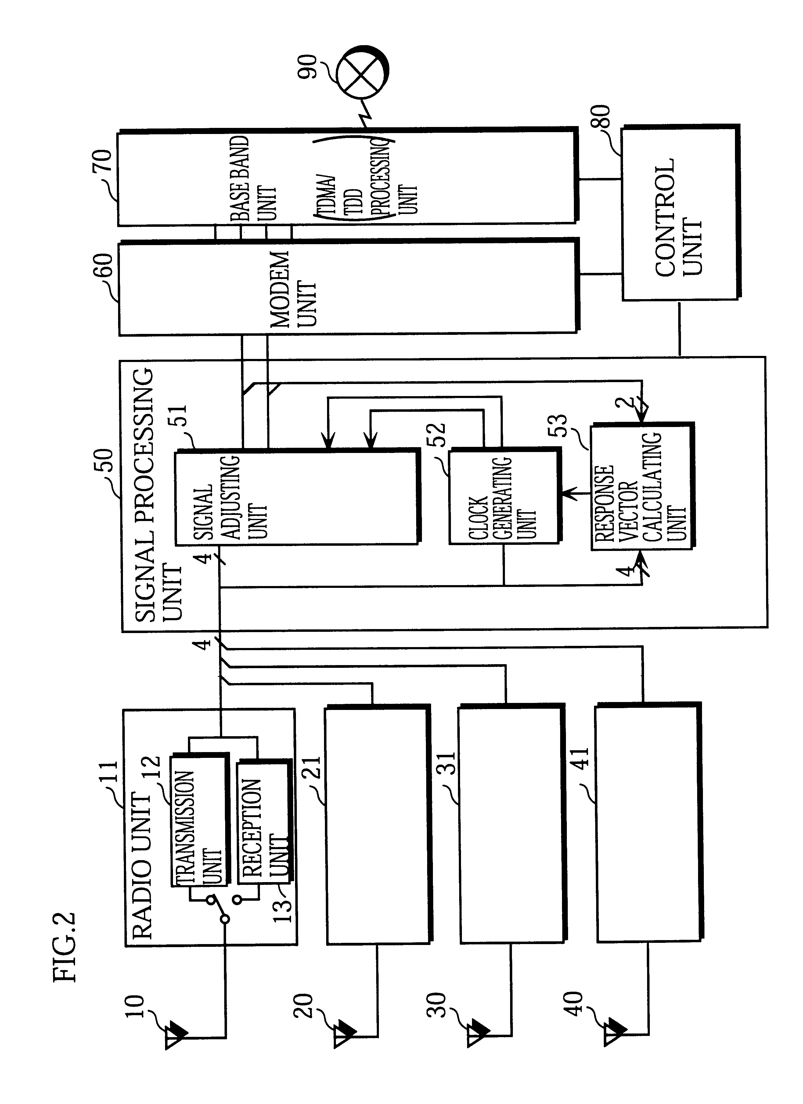
FIG. 2 is a block diagram showing the construction of the main components of a wireless base station that is an embodiment of the present invention.

As shown in FIG. 2, the present wireless base station is composed of radio units 11, 21, 31, and 41, antennas 10, 20, 30, and 40, a modem unit 60, a control unit 80, a baseband unit 70, and signal processing unit 50.

Radio Unit 11

The radio unit 11 is composed of a transmission unit 12 and a reception unit 13. The transmission unit 12 modulates the baseband signal (symbol data) inputted from the signal processing unit 50 to produce an intermediate frequency signal (hereafter, "IF signal"). The radio unit 11 then modulates the IF signal to produce a high-frequency signal (hereafter, "RF signal") which it amplifies to the transmission output level and then outputs to the antenna 10.

The reception unit 13 modulates a received signal inputted from the antenna 10 to produce an IF signal, and then ...

modification 1

While the above embodiment describes an adjustment to the transmission timing of signals for two mobile stations whose signals are multiplexed together using path division, this is not a limitation for the present invention. As one example, suppose that multiplexing is being performed using path division for the signals of three mobile stations (PS-1, PS-2, PS-3). In this case, the transmission of symbol data for the mobile stations PS-2 and PS-3 can be respectively delayed by 0.33 and 0.66 symbol periods relative to the transmission of symbol data for the mobile station PS-1. As a result, mobile stations can be prevented from mistakenly demodulating symbol data that is transmitted to other mobile stations.

In the same way, when N signals are being multiplexed using path division, the transmission timing of symbols for different mobile stations can be set at (K / N).multidot.T from a predetermined point in the timeslot, where K=0, 1, 2, . . . , N-1 and T is the symbol period.

The delayi...

second modification

The above embodiment was described as adjusting the transmission timing of symbols when two mobile stations with spatially multiplexed signals are positioned in similar directions relative to a wireless base station. However, the transmission timing of spatially multiplexed signals may always be adjusted, regardless of the positioning of the mobile stations.

When a wireless base station has a plurality of antennas and a large number of signals can be spatially multiplexed, the transmission timing of symbols to each mobile station will be similar. This makes it easier for mobile stations to demodulate signals that are intended for other mobile stations. In this case, the following method may be used. The wireless base station may first judge whether the number of signals to be multiplexed using path division is equal to or above a predetermined number. When this is not the case, the wireless base station may adjust the transmission timing for all mobile stations currently in communica...


PUM


Abstract

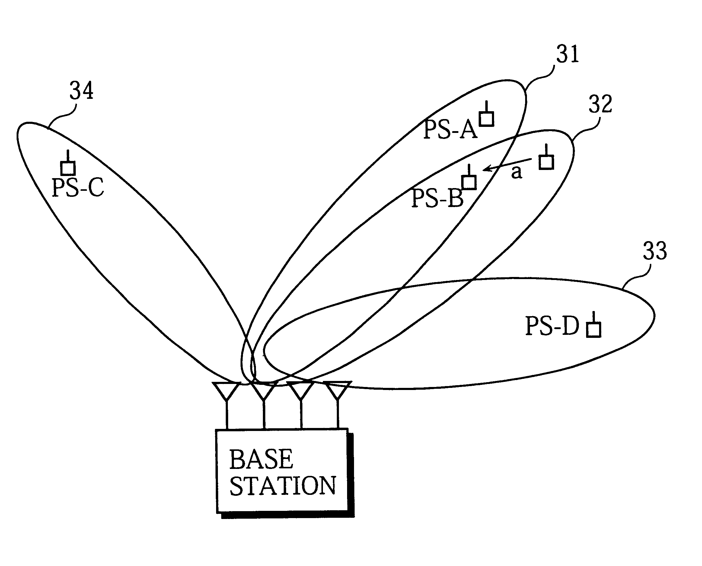
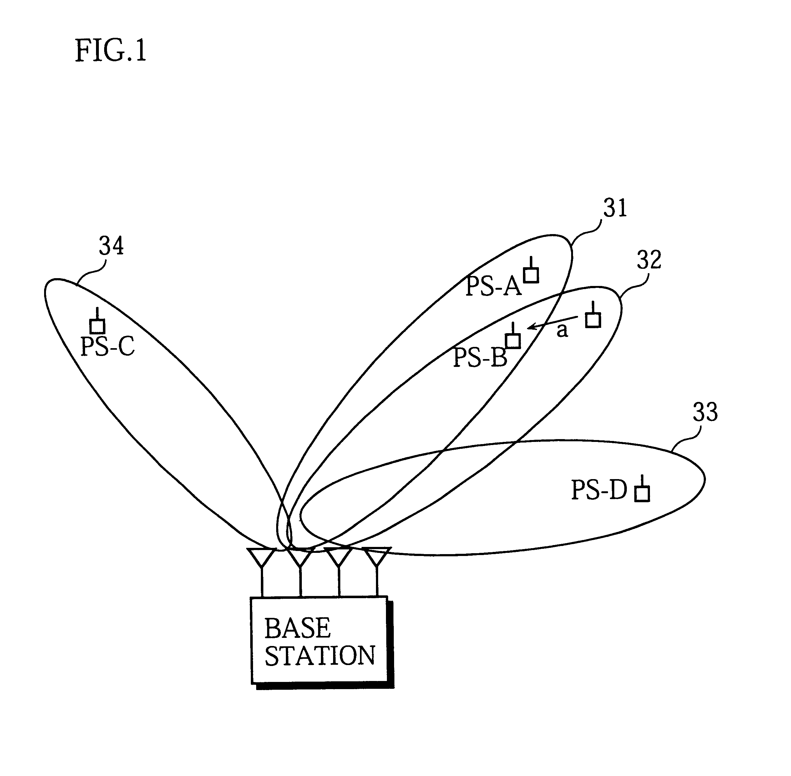
When signals for two mobile stations PS-A and PS-B are multiplexed using path division, a clock generating unit 52 generates a clock signal so as to delay the timing for transmitting symbols to the mobile station PS-B by 0.5 symbol periods relative to the transmission of symbols to the mobile station PS-A. If the transmission timing is adjusted in this way, a mobile station that picks up symbols which are spatially multiplexed with the signal for the present mobile station but are intended for another mobile station will not be synchronized with the symbols for the other mobile station. The mobile station will not be able to properly demodulate the symbols for the other mobile station, and so can be prevented from outputtin

Description

(1) Field of the InventionThe present invention relates to a wireless base station that communicates using an adaptive array method where transmission signals for mobile stations are spatially multiplexed using different directivity patterns.(2) Description of the Prior ArtTo raise transfer efficiency, in recent years digital communication devices have transferred information by modulating a carrier wave using a digital information signal (a baseband signal).In the field of digital communication, frequency resources are being used ever more efficiently due to improvements in transfer speed and to increases in the number of channels that have been achieved by accommodating a plurality of users on the same frequency through time-division multiplexing. Attention is also being focused on spatial multiplexing methods where a number of channels are provided at the same time on a single frequency through the use of an adaptive array.Adaptive array methods dynamically form directivity patte...

Claims


Application Information

Patent Timeline
Patent Type & Authority Patents(United States)
IPC IPC(8): H04B7/08H04B7/04H04Q7/30H04B7/06H04Q7/36H01Q3/26H04B7/10H04B7/26H04J99/00H04W56/00H04W72/12H04W88/08
CPCH04B7/0851H04W56/0015H04B7/0617H04B7/2656
Inventor IINUMA, TOSHINORI
Owner KYOCERA CORP
Learn More