Micro-actuator with interdigitated combs perpendicular to a base

a micro-actuator and comb technology, applied in the field of micro-actuators, can solve the problems of difficult manufacturing, limited application, and difficult to join the top and bottom structures

Inactive Publication Date: 2004-08-24
SAMSUNG ELECTRONICS CO LTD
View PDF20 Cites 13 Cited by
  • Summary
  • Abstract
  • Description
  • Claims
  • Application Information

AI Technical Summary

Problems solved by technology

The prior micro-actuator has a structure driven in the direction of an axis or two axes (x,y-axis) parallel to the plane of the stage or the moving structure, and the application is thus limited.
However, this see-saw driving micro-actuator has a stage back driving structure where the driving comb-type electrodes and the fixed driving comb-type electrodes are arranged at the back of the stage and on the top of the plate corresponding to the back, and since the top and bottom structures are manufactured using two substrates and these are joined together afterward, the manufacture is not easy.
Particularly, it is difficult to join the top and bottom structures if foreign materials exist on at least one of the driving comb-type electrodes and the fixed comb-type electrodes arranged in each structure.

Method used


Image

  • Micro-actuator with interdigitated combs perpendicular to a base
  • Micro-actuator with interdigitated combs perpendicular to a base
  • Micro-actuator with interdigitated combs perpendicular to a base

Examples


Embodiment Construction

)

Hereinafter, preferred embodiments of the present invention will be described in greater detail with reference to the appended drawings.

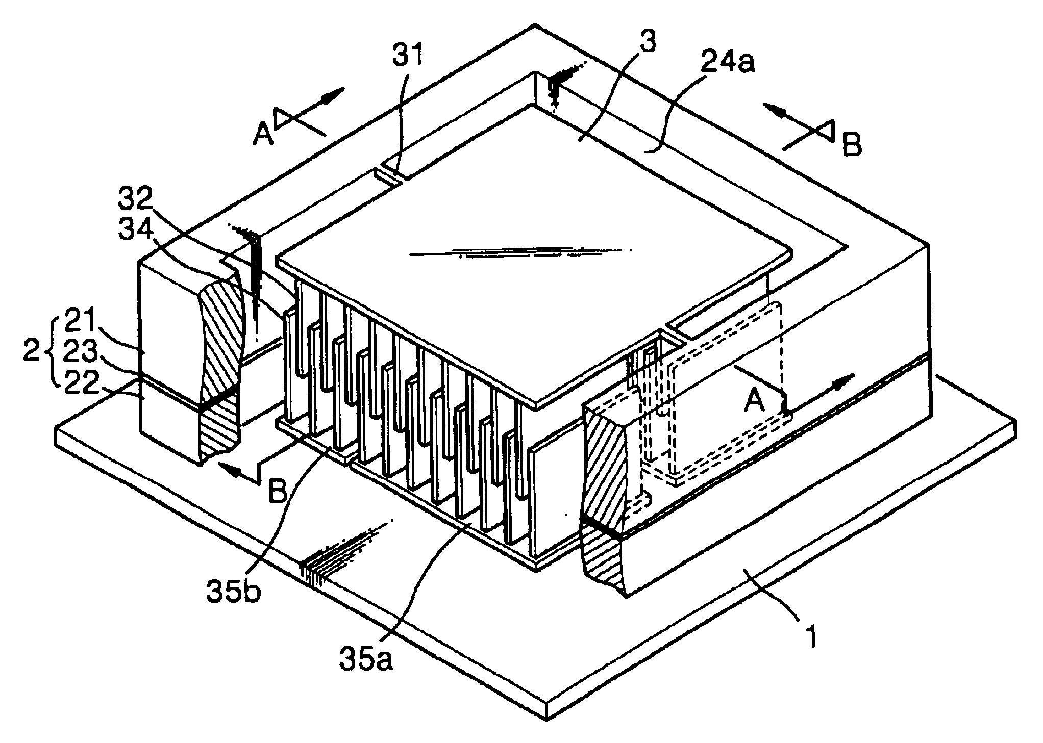
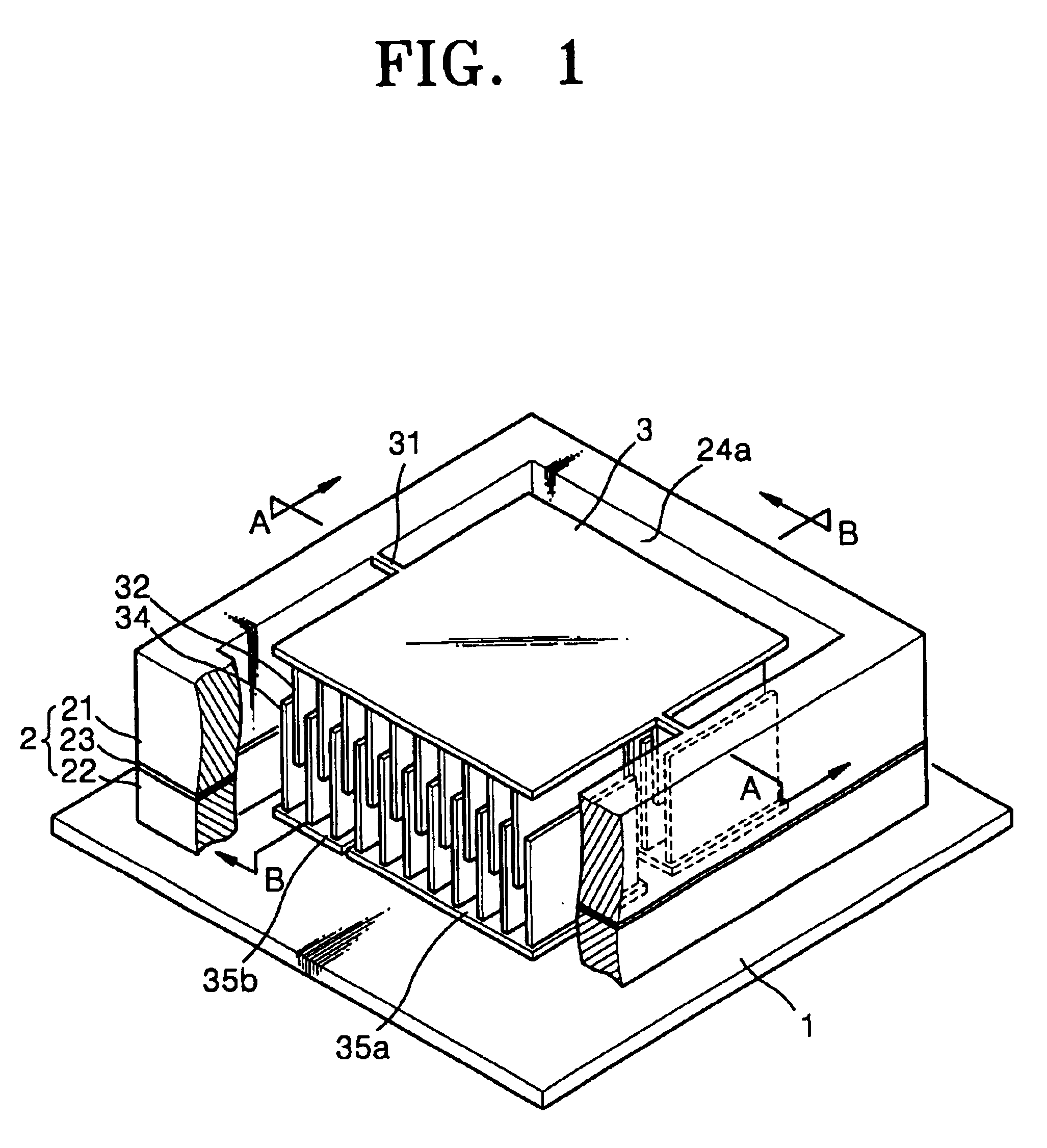
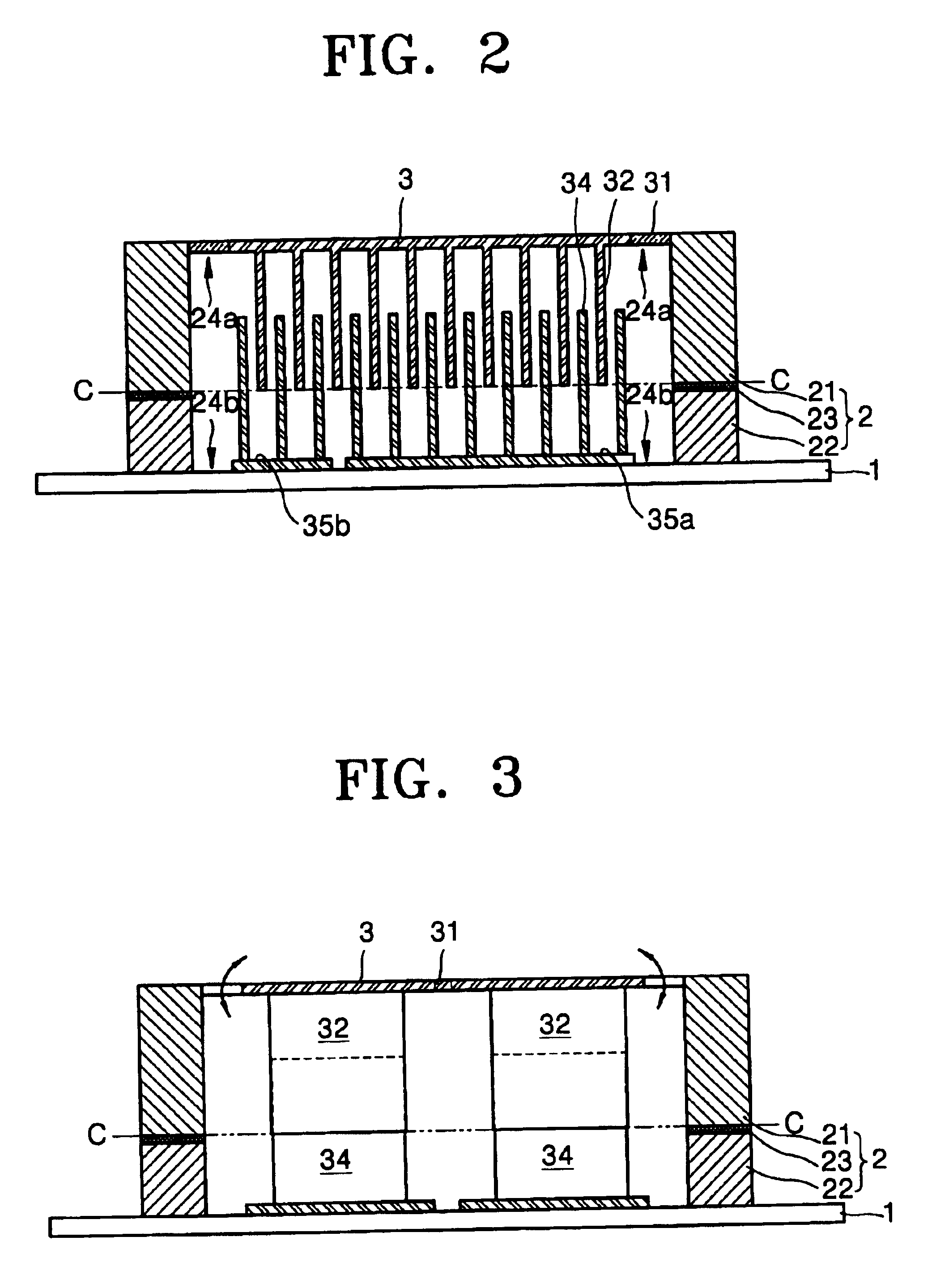
Referring to FIG. 1, a frame 2 in the shape of a rectangular border is situated on a base plate 1 that is made of Pyrex glass, etc. and a stage 3 is positioned inside the frame 2. The stage is supported by a torsion bar 31 that is connected to the frame 2 and extends to the middle part of two ends of the frame 2 which face each other.

The frame 2, the stage 3, and the torsion bar 31 are formed integrally. The frame 2 and the torsion bar 31 provide an electrical path to the stage 3. The torsion bar 31 supports a see-saw motion of the stage 3, and provides an appropriate elastic restoring force upon movement of the stage.

The frame 2 comprises a first frame layer 21 and a second frame layer 22 with a metal eutectic bonding layer plated with Au / Sn alloy between the two frame layer. The first frame layer 21, the stage 3, and the torsion bar 31 are obtain...


PUM

PropertyMeasurementUnit
thicknessaaaaaaaaaa
thickaaaaaaaaaa
thicknessaaaaaaaaaa

Abstract

A micro-actuator having a stage capable of a see-saw motion and a method for its manufacture are disclosed. In the micro-actuator according to the present invention, a plurality of parallel driving comb-type electrodes are formed on the bottom of the stage, and a plurality of parallel fixed comb-type electrodes are formed on a base plate. At both sides of the stage is a torsion bar that enables the see-saw motion. The torsion bar is supported by a frame comprised of a first frame layer and a second frame layer. The torsion bar and the first frame layer form one body. The first and second frame layers are bonded by a metal eutectic bonding layer between metal layers.

Description

1. Field of the InventionThe present invention relates to a micro-actuator operated by electrostatic force and a manufacturing method thereof, and more particularly, to a micro-actuator driven in a see-saw motion in an axial direction and a manufacturing method thereof.2. Description of the Related ArtU.S. Pat. No. 5,025,346 discloses a micro-actuator operated by the electrostatic force induced by the structure of a comb-type electrode. The micro-actuator disclosed in U.S. Pat. No. 5,025,346 has a structure with a plurality of moving comb-type electrodes and a plurality of fixed comb-type electrodes arranged alternately on a moving structure and a fixed structure, respectively. The moving structure is suspended by a surrounding supporting structure and the suspended structure is driven at a resonant frequency in the horizontal direction.To drive in the direction of more than 1 axis such as the x-axis and the y-axis, if driving is in one direction along one axis, more than 3 electrod...

Claims


Application Information

Patent Timeline
Patent Type & Authority Patents(United States)
IPC IPC(8): B81B3/00B81C1/00B81C3/00H02N1/00
CPCB81C3/001B81C1/00142B81B2201/033B81B2203/0136B81B2203/0181B81B2203/04B81B2203/058Y10T29/42B81C2201/0132B81C2203/038Y10T29/435B81C3/00
Inventor LEE, JIN-HOKO, YOUNG-CHULKONG, DO-HYUN
Owner SAMSUNG ELECTRONICS CO LTD
Why Eureka
Try Eureka