Micro actuator DC gain calibration scheme for HDD dual-stage actuator systems

a dual-stage actuator and micro-actuator technology, applied in the direction of maintaining head carrier alignment, recording information storage, instruments, etc., can solve the problems of difficult implementation of the servo system, difficult technique, and easy gain drift of the actuator using the voltage driver

Inactive Publication Date: 2005-12-13
MAXTOR
View PDF3 Cites 32 Cited by
  • Summary
  • Abstract
  • Description
  • Claims
  • Application Information

AI Technical Summary

Benefits of technology

[0034]The present invention may be embodied as a servo system for displacing a head relative to a disk of a hard drive. The servo system comprises a dual-stage actuator, a calibration signal generator, and a calibration factor generator. The calibration signal generator generates a calibration signal having a calibration portion. The calibration factor generator generates a calibration factor. The servo system operates in operating and calibration servo modes. In the operating mode, the system defines first and second servo loops. The calibration factor is used as one of the parameters of the second servo loop. In the calibration servo mode, the calibration signal forms the second control signal, and the calibration factor generator generates the calibration factor based on movement of the head before any substantial response of the third servo loop to the calibration portion.

Problems solved by technology

An actuator using a voltage driver is susceptible to gain drifts with changing temperatures.
This technique thus does not work well when applied to the second stage actuator structure 32 of a hard disk drive.
The process of measuring the error transfer function complicates implementation of the servo system 60 and increases the likelihood that the calibration will be inaccurate.
Even if the nominal VCM plant is used and it is assumed that, at low frequencies, the gain variation of the VCM is negligible, this second calibration approach is still susceptible to the problem of low coherence.

Method used


Image

  • Micro actuator DC gain calibration scheme for HDD dual-stage actuator systems
  • Micro actuator DC gain calibration scheme for HDD dual-stage actuator systems
  • Micro actuator DC gain calibration scheme for HDD dual-stage actuator systems

Examples


Embodiment Construction

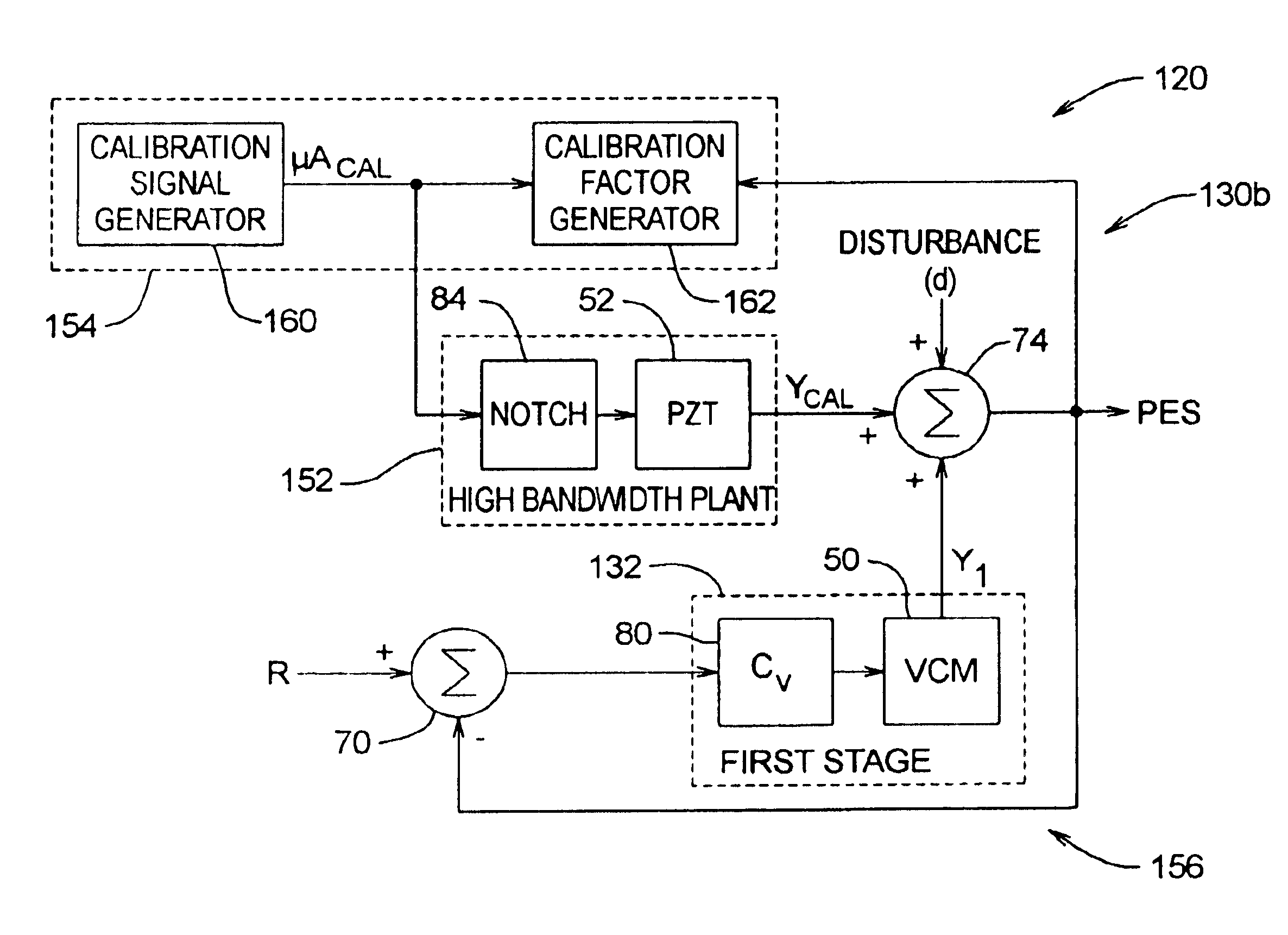
[0045]Referring now to FIGS. 5 and 6 of the drawing, depicted therein is a servo system 120 constructed in accordance with, and embodying, the principles of the present invention. The exemplary servo system 120 operates in a read / write servo (operating) mode 130a as shown in FIG. 6 and a calibration servo mode 130b as shown in FIG. 5.

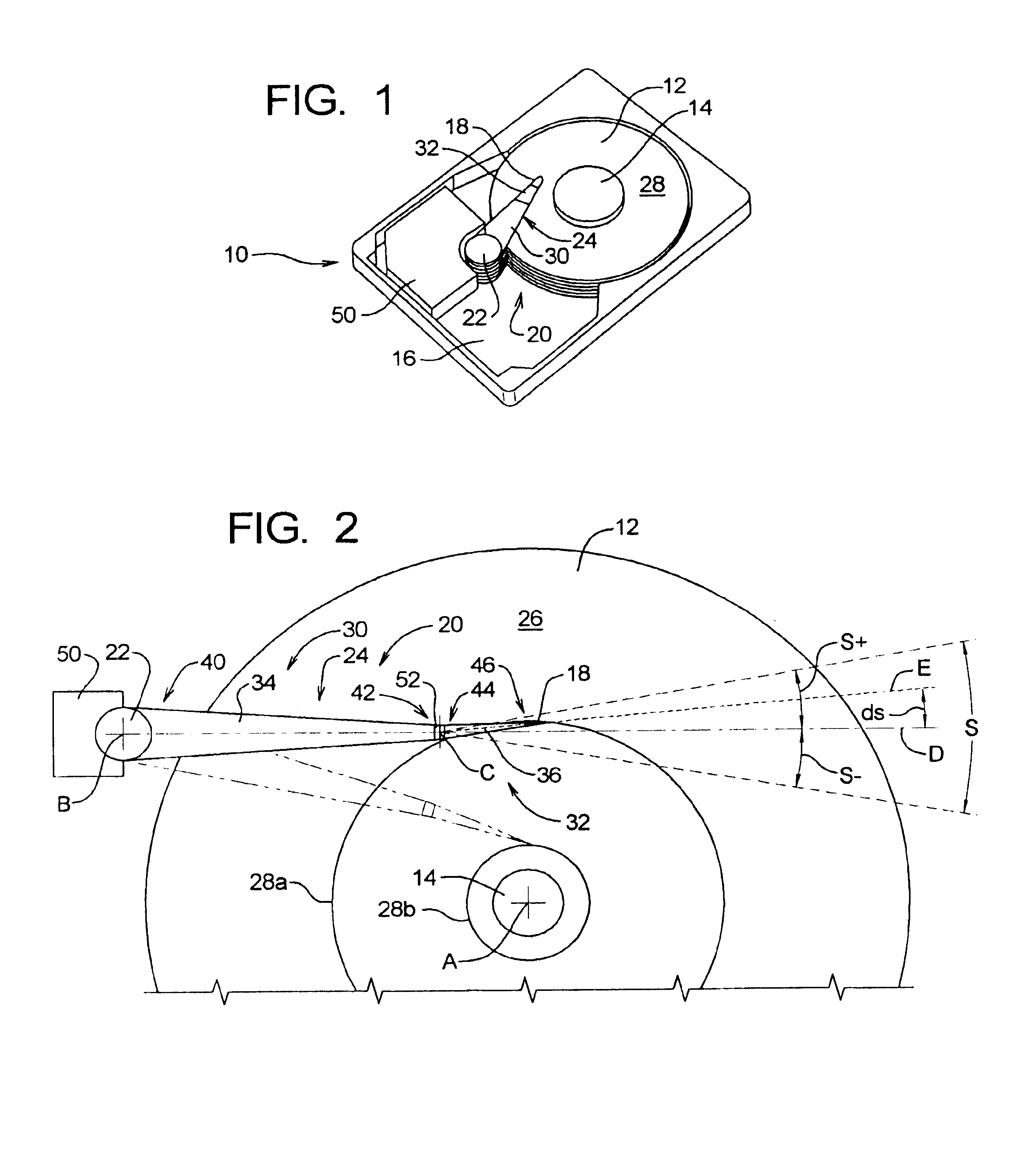
[0046]In both the calibration servo mode 130b and the read / write servo mode 130a, the servo system 120 comprises an actuator system comprising the first and second actuator structures 30 and 32 and first and second actuators 50 and 52 described above. As will be described in detail below, the servo system 120 further generates the first and second actuator control signals that cause the actuators 50 and 52 to move the actuator structures 30 and 32.

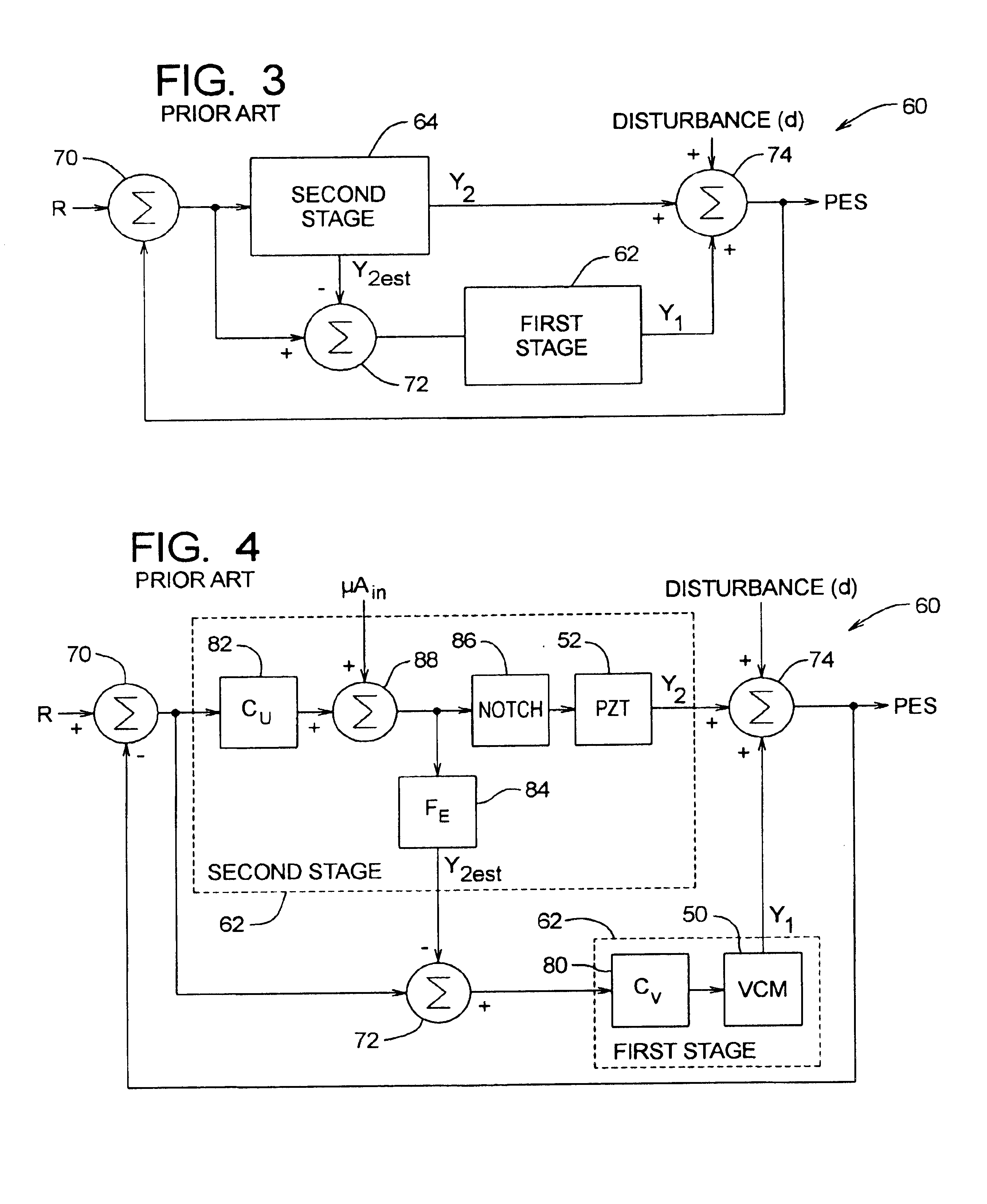
[0047]As shown in FIG. 6, when in the read / write servo mode 130a, the servo system 120 is configured to define a dual-stage servo system. The servo system 120 will typically be embodied as a software program r...


PUM

PropertyMeasurementUnit
radiusaaaaaaaaaa
magneticaaaaaaaaaa
magnetic fieldaaaaaaaaaa

Abstract

A servo system for displacing a head relative to a disk of a hard disk drive. The servo system comprises a dual-stage actuator, a calibration signal generator, and a calibration factor generator. The calibration signal generator generates a calibration signal having a calibration portion. The calibration factor generator generates a calibration factor. The servo system operates in operating and calibration servo modes. In the operating mode, the system defines first and second servo loops. The calibration factor is used as one of the parameters of the second servo loop. In the calibration servo mode, the calibration signal forms the second control signal, and the calibration factor generator generates the calibration factor based on movement of the head before any substantial response of the third servo loop to the calibration portion.

Description

RELATED APPLICATIONS[0001]Priority is claimed from U.S. Provisional Patent Application Ser. No. 60 / 377,927 filed on May 3, 2002, which is incorporated by reference in its entirety.FIELD OF THE INVENTION[0002]The present invention relates to digital storage devices and, more particularly, to actuator systems for hard disk drives.BACKGROUND OF THE INVENTION[0003]A disk drive is a digital data storage device that stores information on concentric tracks on a storage disk. The storage disk is coated on one or both of its primary surfaces with a magnetic material that is capable of changing its magnetic orientation in response to an applied magnetic field. During operation of a disk drive, the disk is rotated about a central axis at a constant rate. To read data from or write data to the disk, a magnetic transducer (or head) is positioned above (or below) a desired track of the disk while the disk is spinning.[0004]Writing is performed by delivering a polarity-switching write current sign...

Claims


Application Information

Patent Timeline
Patent Type & Authority Patents(United States)
IPC IPC(8): G11B5/55G11B5/596G11B15/18
CPCG11B5/5552G11B5/596
Inventor HU, XIAOPINGGUO, LINGUO, WEILIN, JONG-MING
Owner MAXTOR
Why Eureka
Try Eureka