Electromagnetic actuator

a micro actuator and actuator technology, applied in the direction of electromagnets, magnetic bodies, electrical appliances, etc., can solve the problems of micro actuators being subject to temperature and environmental fluctuations, and the design of actuators limiting the size reduction of switches

Inactive Publication Date: 2002-10-24
R AUDEMARS
View PDF0 Cites 34 Cited by
  • Summary
  • Abstract
  • Description
  • Claims
  • Application Information

AI Technical Summary

Problems solved by technology

However, current micro actuator design places limits on switch size reductions.
Moreover, current micro actuators may be subject to temperature and environmental fluctuations, particularly because they employ materials that can expand and contract due to temperature fluctuations.

Method used


Image

  • Electromagnetic actuator
  • Electromagnetic actuator
  • Electromagnetic actuator

Examples


Embodiment Construction

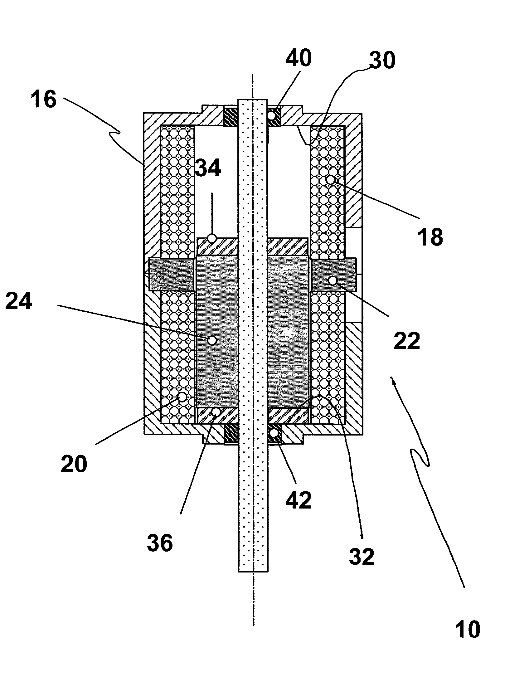
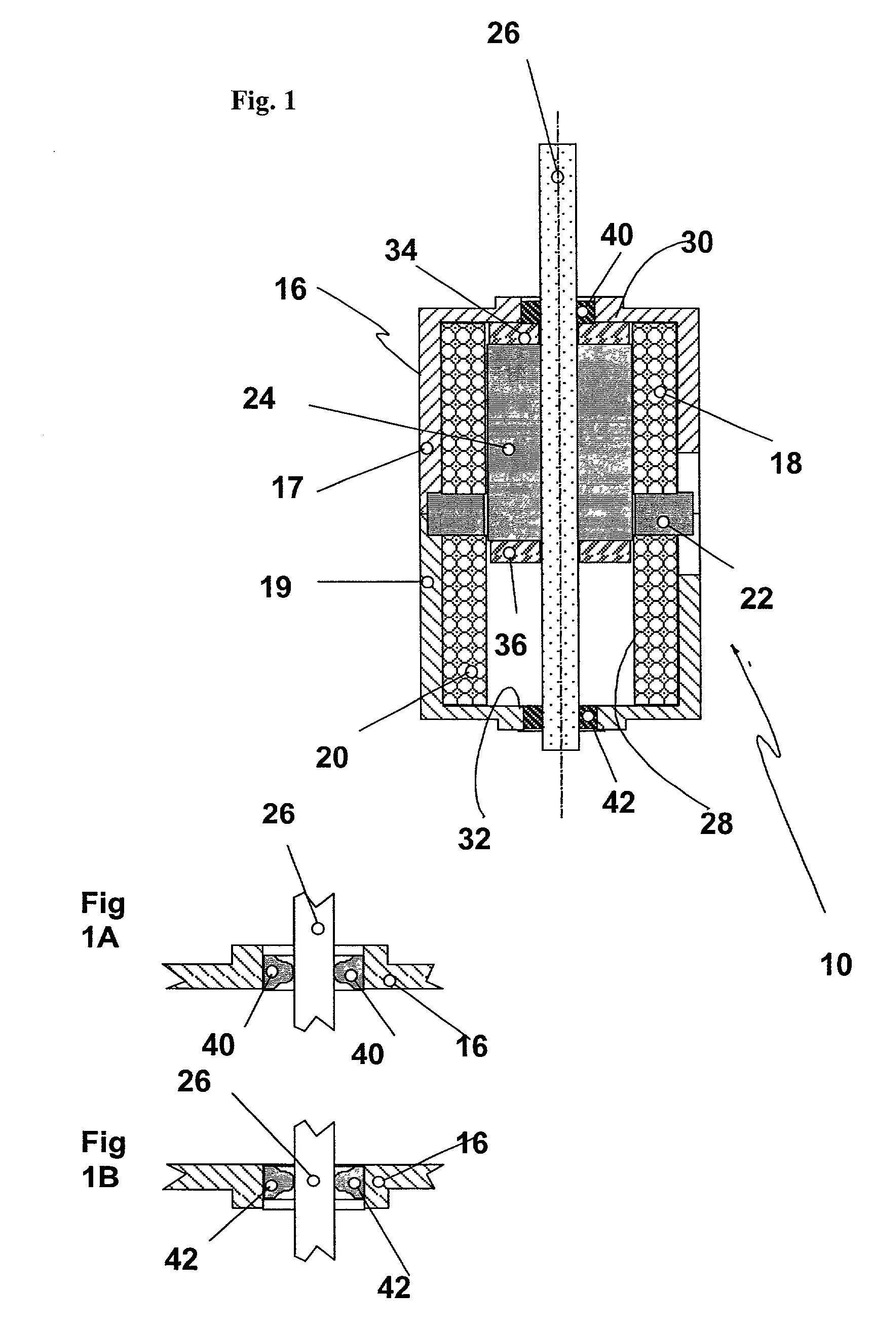
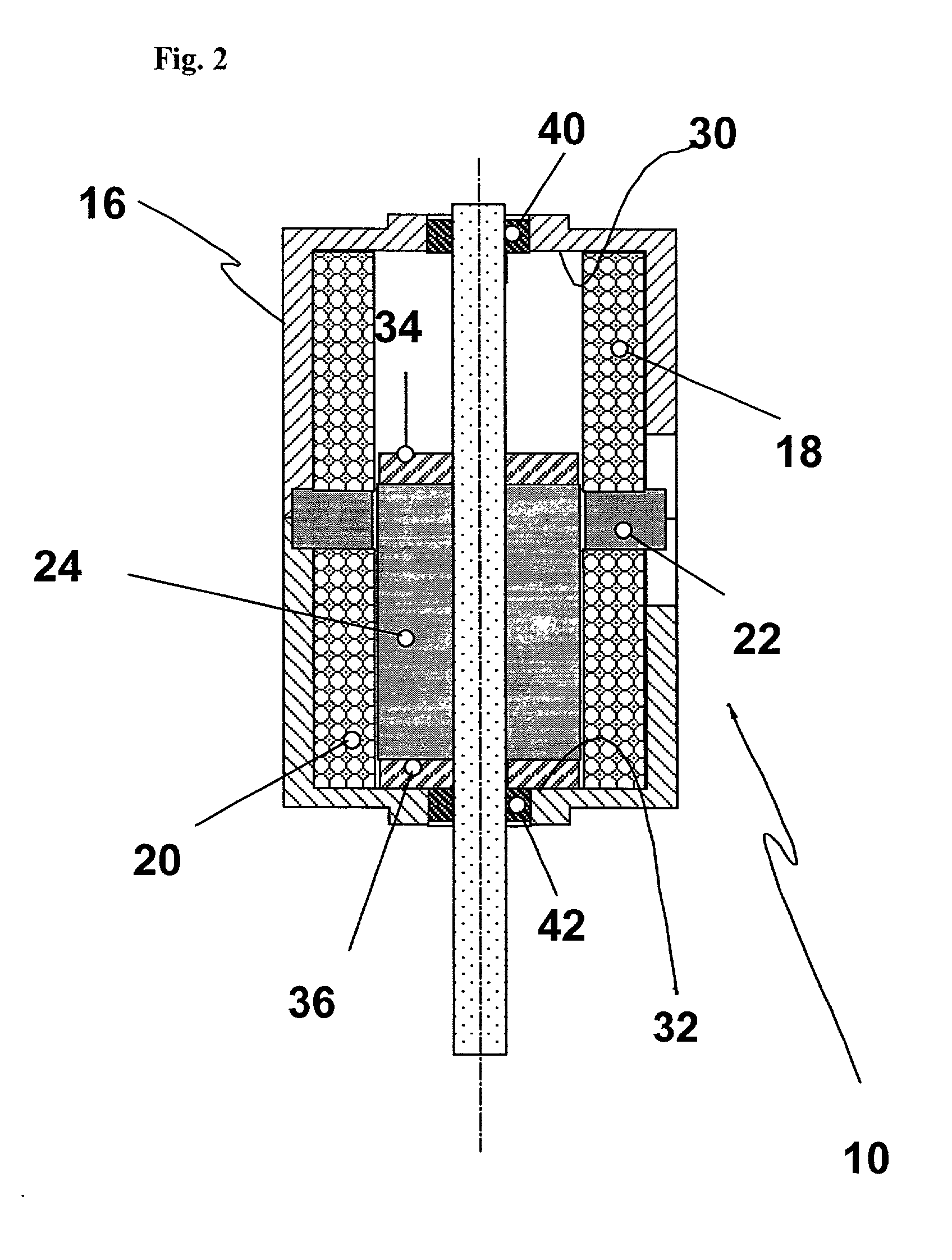
[0015] Referring now to the drawings, wherein like numerals indicate like elements, FIG. 1 shows a micro actuator according to the present invention. The presently preferred embodiment of micro actuator 10 may be used in an optical switch to control the direction of laser beams between two collimators (not shown). However, its use is not so limited. It can be used in any environment requiring a linear latched movement, especially one requiring a linear actuator of small size and fast switching time.

[0016] The micro actuator 10 includes a cylindrical housing 16, a pair of electromagnetic coils 18, 20 arrayed next to each other along the axis of the housing, a permanent magnet 22 placed between the coils and midway between the ends of the passage in the housing 16 and a piston 24 carried on a rod or shaft 26. The permanent magnet 22 and the electromagnetic coils 18, 20 cooperate to toggle the piston 24 between two latched positions, one to the top end of the passage in the housing 16 ...


PUM

PropertyMeasurementUnit
diameteraaaaaaaaaa
lengthaaaaaaaaaa
lengthaaaaaaaaaa

Abstract

An electromagnetic micro actuator, e.g. for use in fiber optics, is operated by a ferromagnetic piston mounted within two electromagnetic coils inside a housing. The piston is held in place and magnetized by a plurality of permanent magnets. The coils are wired for opposite polarity and energizing the coils will tend to push the piston away from one coil and draw it towards another. A ceramic shaft attached to the piston protrudes from both ends of the micro actuator housing and moves with said piston. Energizing the coils thus moves the piston in one or the opposite direction depending on the current direction. Tapered jewel bearings guide the shaft with minimal friction.

Description

[0001] 1. Field of the Invention[0002] The present invention relates to a micro actuator, particularly useful for optical switches, two electromagnetic coils moving a piston between two latched positions control the actuator.[0003] 2. Description of Related Art[0004] In the field of fiber-optic communications, there is a need for electromechanical micro-actuated optical switches. The function of the switch is to direct / redirect laser beams from one channel to another within a maximum of time of 10 ms. These switches are typically electromechanical and operate by moving a mirror or filter to either permit or deviate passage of a laser beam through a gate. The switch toggles between two latched positions to operate as a binary switch. By placing the switches in a matrix coupled by fiber-optic collimators, it is possible to control the passage of information through the matrix. Due to the limited distance through which a laser beam can travel in free space between two collimators, it i...

Claims


Application Information

Patent Timeline
Patent Type & Authority Applications(United States)
IPC IPC(8): H01F7/122H01F7/16
CPCH01F7/1615H01F7/122
Inventor JONES, PETERREGGIANI, ALDO
Owner R AUDEMARS
Why Eureka
Try Eureka