Ballast with lamp sensor and method therefor

a technology of electronic ballast and lamp sensor, which is applied in the field of electronic ballast, can solve the problems of lamp filling, lamp overheating and failure of the switch device commonly found in the electronic ballast circuit, and the lamp may become deactivated, so as to minimize the possibility of components overheating or failing, and the cost is low

Inactive Publication Date: 2004-08-24
Q TECH CO LTD
View PDF10 Cites 27 Cited by
  • Summary
  • Abstract
  • Description
  • Claims
  • Application Information

AI Technical Summary

Benefits of technology

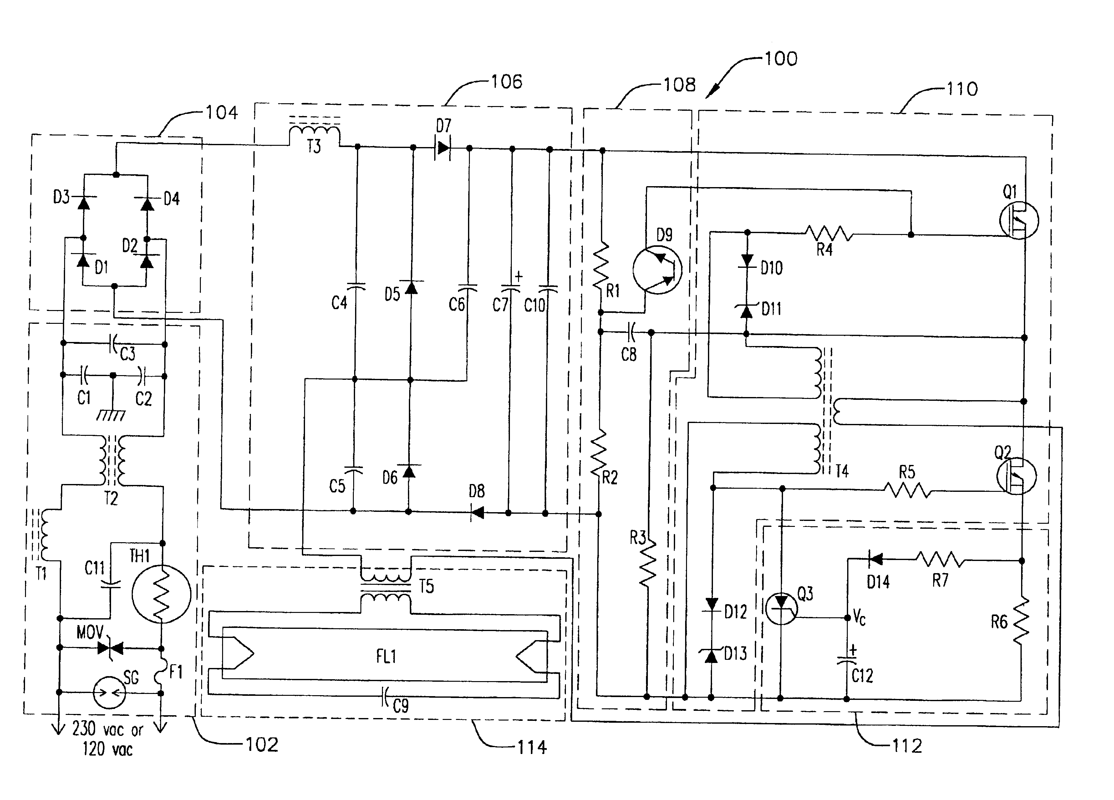
A ballast is provided herein which includes a circuit, component or method for detecting and / or protecting a ballast or its components from abnormal or undesirable lamp conditions or wiring configurations. The ballast according to the present invention may include a circuit that is more simple and lower in cost than other ballasts, and more reliable. In one form of the invention, the ballast can be restarted without having to be reset, and may include a suitable protective delay in restarting to minimize the possibility of components overheating or failing.
In another form of one of the present inventions, the ballast circuit having a protection circuit and a response circuit includes a plurality of diodes in the protection circuit. The response circuit includes a current conduction path, and the ballast circuit may further include at least one transistor for producing current for driving the lamp, wherein the current conduction path is coupled to a gate of the transistor. In one preferred embodiment, the response circuit includes a delay so that current to the lamp is not removed prematurely.
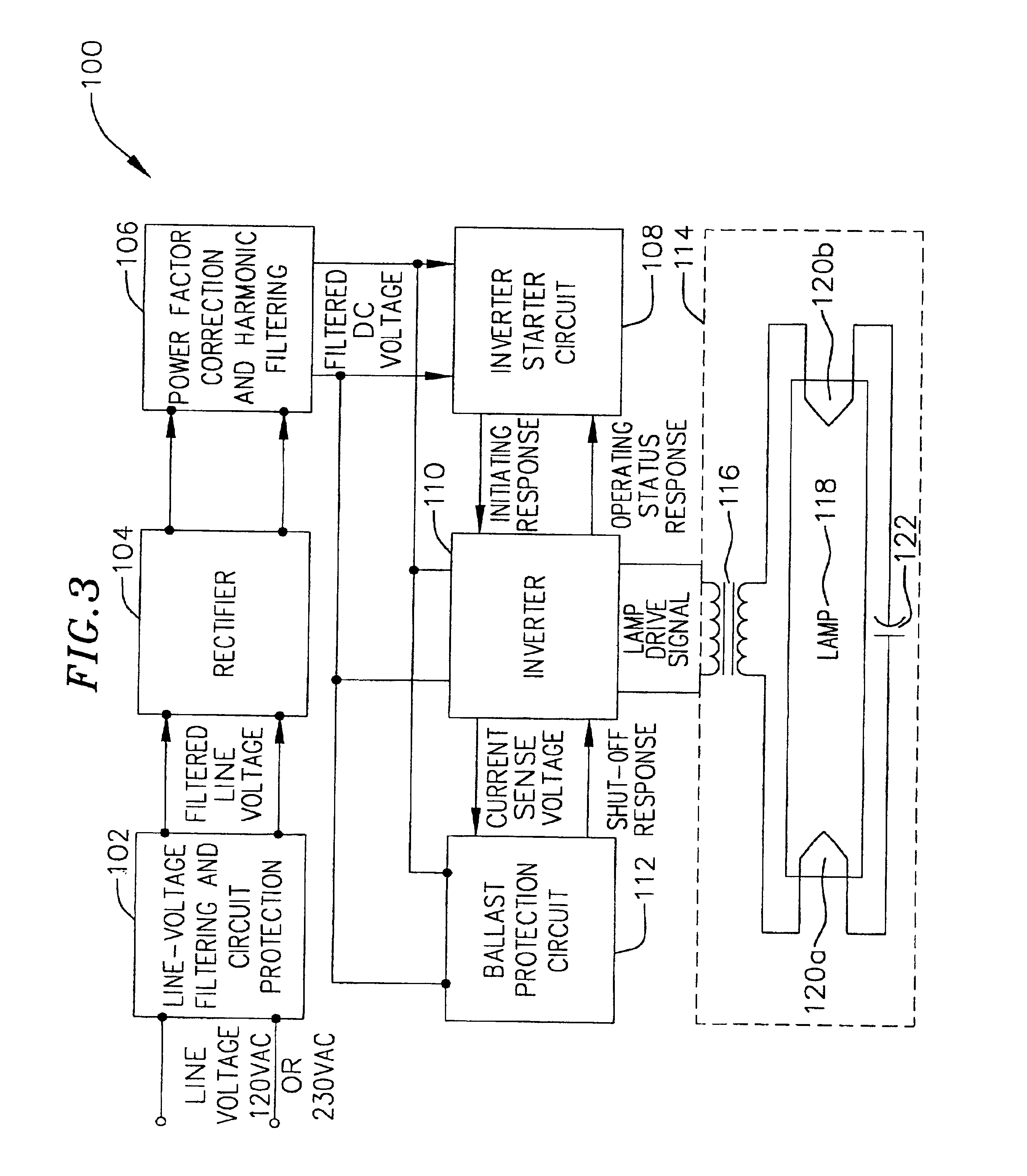
In one form of the inventions, a ballast circuit is provided having an input, an output for coupling to an electric discharge lamp and an oscillation circuit for illuminating the lamp. A circuit may be included for sensing when current from the oscillation circuit exceeds acceptable levels, at which point, the ballast circuit may be shut down, limited or otherwise reducing the possibility of ballast failure. In one form of the invention, a ballast protection circuit or, more specifically, a current excursion sensor circuit is coupled between the oscillation circuit and the output circuit for sensing when the current from the oscillation circuit exceeds a given value. Preferably, the invertor circuit is shut down and maintained inactive until such time as any current excursion has a chance to decay away, ballast components have an opportunity to cool off or otherwise return to normal condition or until such other condition has occurred. Preferably, the ballast is shut down upon a current or voltage excursion of such a magnitude at or before components may overheat or begin to fail.
In one form of the invention, a sensor circuit includes a silicon-controlled rectifier (SCR) for stopping, interrupting or shunting current in the ballast in order to shut the ballast down. Where the oscillation circuit includes switching transistors, the SCR can turn off one or both of the transistors to shut off the ballast. A capacitor may be included in the sensor circuit to help control the SCR, and may also provide a delay for preventing the ballast from restarting before conditions approach normal.
In yet another aspect of the invention, a method of protecting a ballast circuit from generating a lamp drive current that is excessive is provided herein, comprising the steps of sensing a current sensing voltage across a current sensing resistor that varies as a function of the lamp drive current; and preventing the ballast circuit from generating said lamp drive current if the current sensing voltage is within a predetermined voltage range indicating that an excessive lamp drive current exists.

Problems solved by technology

As a result, switching devices commonly found in electronic ballast circuits may overheat and fail.
In another example, a lamp may become deactivated, wherein the gas fill of the lamp is either dissipated during use or was not present in sufficient amounts to efficiently fire the lamp.
Even though the filaments of the lamp are acceptable, the lamp does not properly fire.
The lamp no longer exhibits the necessary resistance to maintain the desirable impedance in the circuit, thereby presenting a relatively low impedance to the ballast.
The ballast components operating at such high power levels may overheat and fail.
Occasionally, lamps may be improperly wired to a ballast, which may present a low impedance to the ballast.
Another factor possibly affecting ballast performance includes incoming line voltages.
Significant voltage variations as seen by the ballast may therefore also cause component overheating and possible ballast failure.
However, such circuits may be relatively expensive, include a relatively large number of components, or may require resetting the ballast before the ballast can again begin operation.

Method used


Image

  • Ballast with lamp sensor and method therefor
  • Ballast with lamp sensor and method therefor
  • Ballast with lamp sensor and method therefor

Examples


Embodiment Construction

Fluorescent lamps are used in many applications for providing lighting for commercial buildings, houses, warehouses, parking lots and other applications. One particular application of interest to the invention is the illumination of refrigeration systems. A fluorescent lamp driving circuit, typically termed a ballast, is usually employed in conjunction with the lamp to provide it a lamp drive current for causing the lamp to start illuminating, and to keep the lamp illuminated during normal operations.

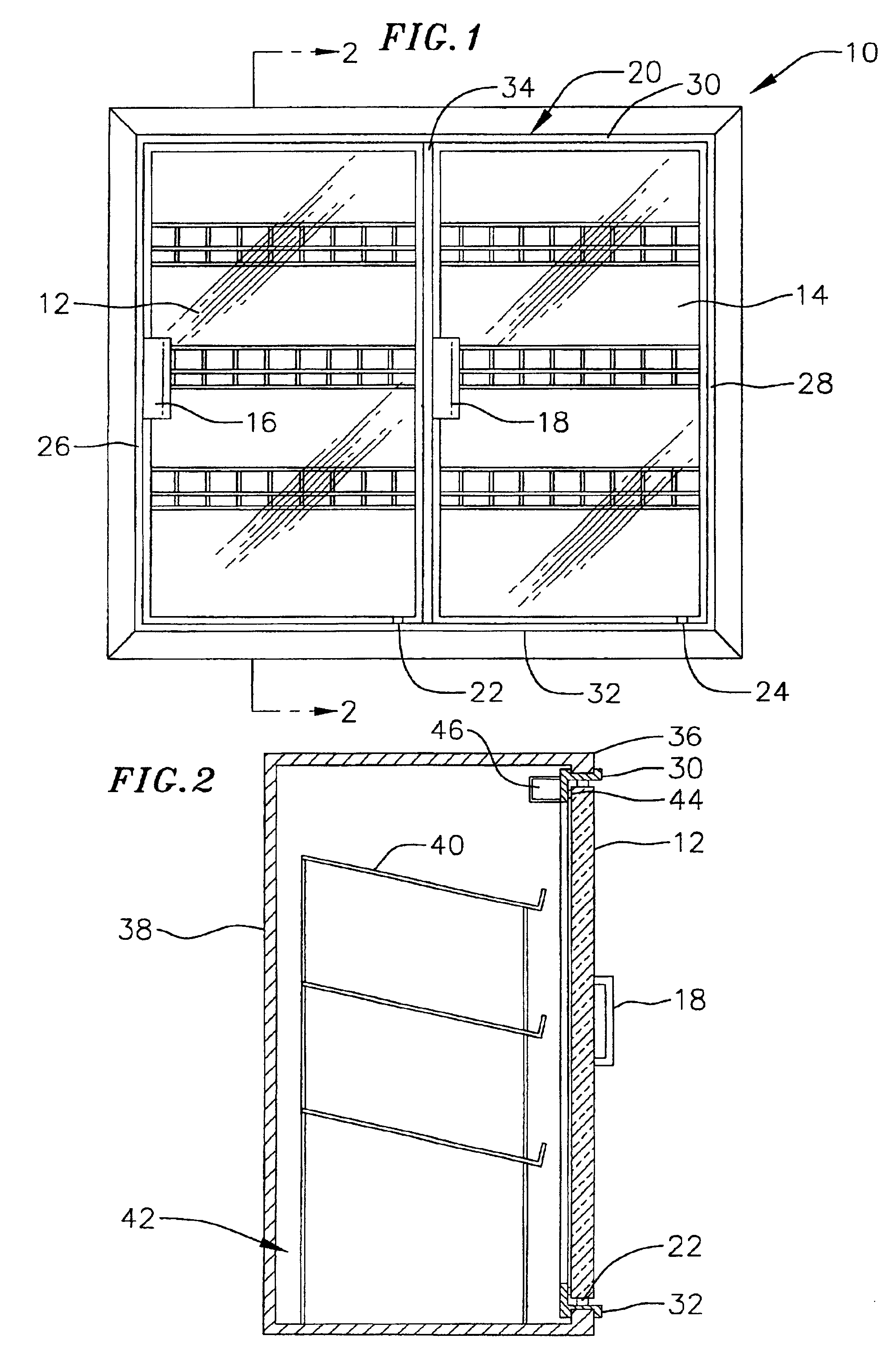
FIG. 1 illustrates one example of a refrigeration unit 10 which may be used in conjunction with, or from an element of, the present inventions. The refrigeration unit may be either a stand alone unit or a "built-in" unit. The refrigeration unit includes a pair of doors 12 and 14 which include handles 16 and 18, respectively. The doors 12 and 14 are pivotally mounted on a frame 20 by hinges 22 and 24. Frame 20 is secured to an opening in the refrigeration unit and consists of a pair of s...


PUM


Abstract

A ballast circuit is provided having an input, an output for coupling to an electric discharge lamp and an oscillation circuit for illuminating the lamp. A circuit may be included for sensing when a voltage on an input to the oscillation circuit exceeds desired levels. The ballast circuit may be shut down, limited or otherwise controlled to reduce the possibility of ballast failure.

Description

FIELD OF INVENTIONSThese inventions relate to electronic ballasts.BACKGROUND OF THE INVENTIONSGas discharge lamps such as fluorescent lamps require ballast in order to properly start and maintain lamp ignition to produce adequate light from the lamp. Ballast may be of electromagnetic, electronic or solid state types. With newer lamps, electronic ballast have been required in order to provide the necessary voltage and current to start the lamp and to maintain the required light output.As a fluorescent lamp ages, several things can occur. For example, an emissive coating on the lamp filament may become depleted to the point the voltage drop from the filament to the arc stream is significantly increased because ionization of the gas in the lamp decreases due to the decrease in filament electron production. This causes the ballast to increase the voltage across the filament in an attempt to increase the current through the lamp in trying to provide the power apparently required by the l...

Claims


Application Information

Patent Timeline
Patent Type & Authority Patents(United States)
IPC IPC(8): H05B41/285H05B41/28
CPCH05B41/2853H05B41/2855
Inventor STACK, TOM
Owner Q TECH CO LTD
Why Eureka
Try Eureka