Rotatable tool with removable cutting part

a cutting part and rotating technology, applied in the direction of manufacturing tools, cutting inserts, twist drills, etc., can solve the problems of inability to integrate with the cutting part, cutting edges cannot be formed in the central area of the front end of the cutting part, and the cutting part is so sophisticated and expensiv

Inactive Publication Date: 2004-08-31
SANDVIK INTELLECTUAL PROPERTY AB
View PDF14 Cites 21 Cited by
  • Summary
  • Abstract
  • Description
  • Claims
  • Application Information

AI Technical Summary

Benefits of technology

The present invention aims at obviating the above-mentioned disadvantages of previously known cutting tools of the type in question and at providing an improved cutting tool. Thus, a primary object of the invention is to provide a cutting tool that not only allows simple mounting and dismounting of the cutting unit without requiring that the holder part be removed from a machine, but also enables cutting edges or cutting inserts to be disposed at the center of the front surface of the cutting part. An additional object is to provide a tool, the two main parts of which, i.e., the cutting part and the holder part, respectively, can be series produced separately in a simple and cost-effective way while guaranteeing a good centering of the cutting part in relation to the holder part. Among other things, each one of the two parts should be able to be produced by means of simple machining operations and with a minimum of advanced grinding operations. Yet an object of the invention is to provide a tool that minimizes the wear of the holder part, thereby securing a long service life of the same.

Problems solved by technology

In modern machine tools, the holder parts are so sophisticated and expensive that they, for economical reasons, cannot be integrated with the cutting part, which constitutes the wearing part of the tool.
A disadvantage of said kind of tool is, however, that cutting edges cannot be formed in the central area of the front end of the cutting part.
The consequence of this is that the cutting part can only be made for certain types of milling (e.g., milling of T-slots), but not for drilling and other milling operations.
A disadvantage of said type of tools is, however, that tightening of the drawbar takes place in the area of the rear end of the drawbar and the holder part.
A disadvantage of said tool is, however, that the cutting part as well as the holder part has to be manufactured with a very high dimensional accuracy.
Another disadvantage is that the tool demands dismounting from the appurtenant machine in order to enable manipulation of the screw in connection with exchange of the cutting part.

Method used


Image

  • Rotatable tool with removable cutting part
  • Rotatable tool with removable cutting part
  • Rotatable tool with removable cutting part

Examples


Embodiment Construction

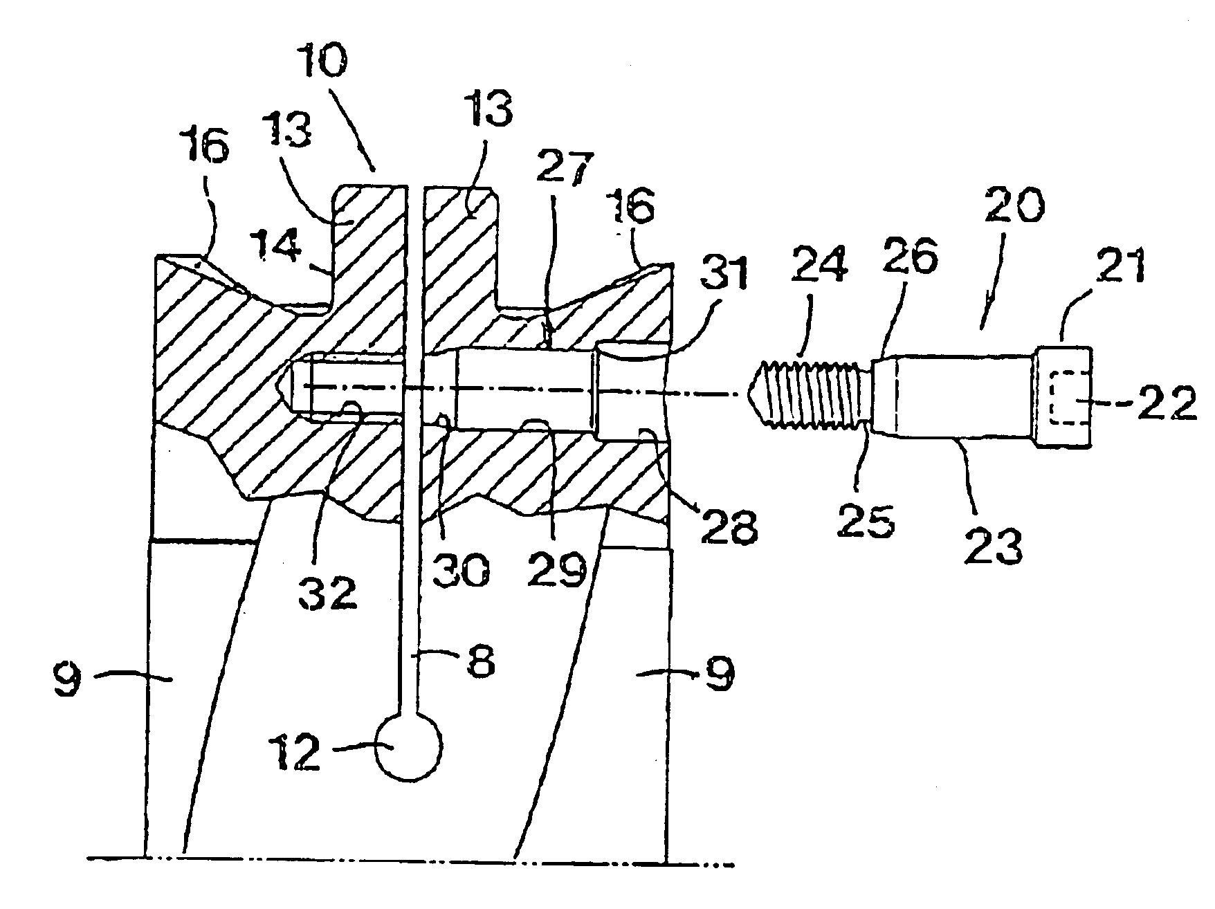
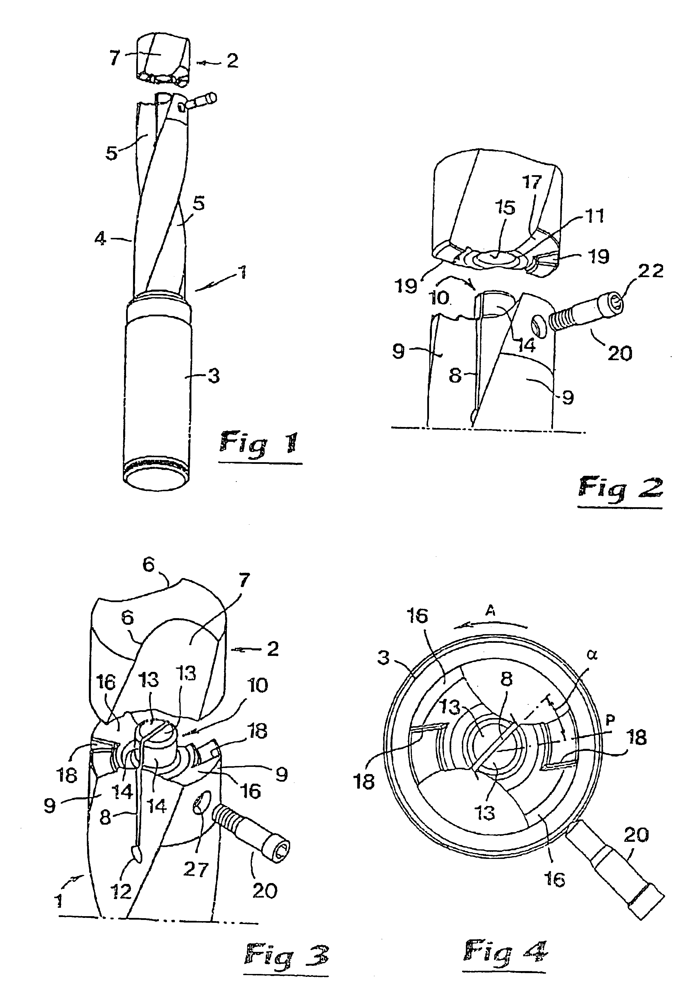
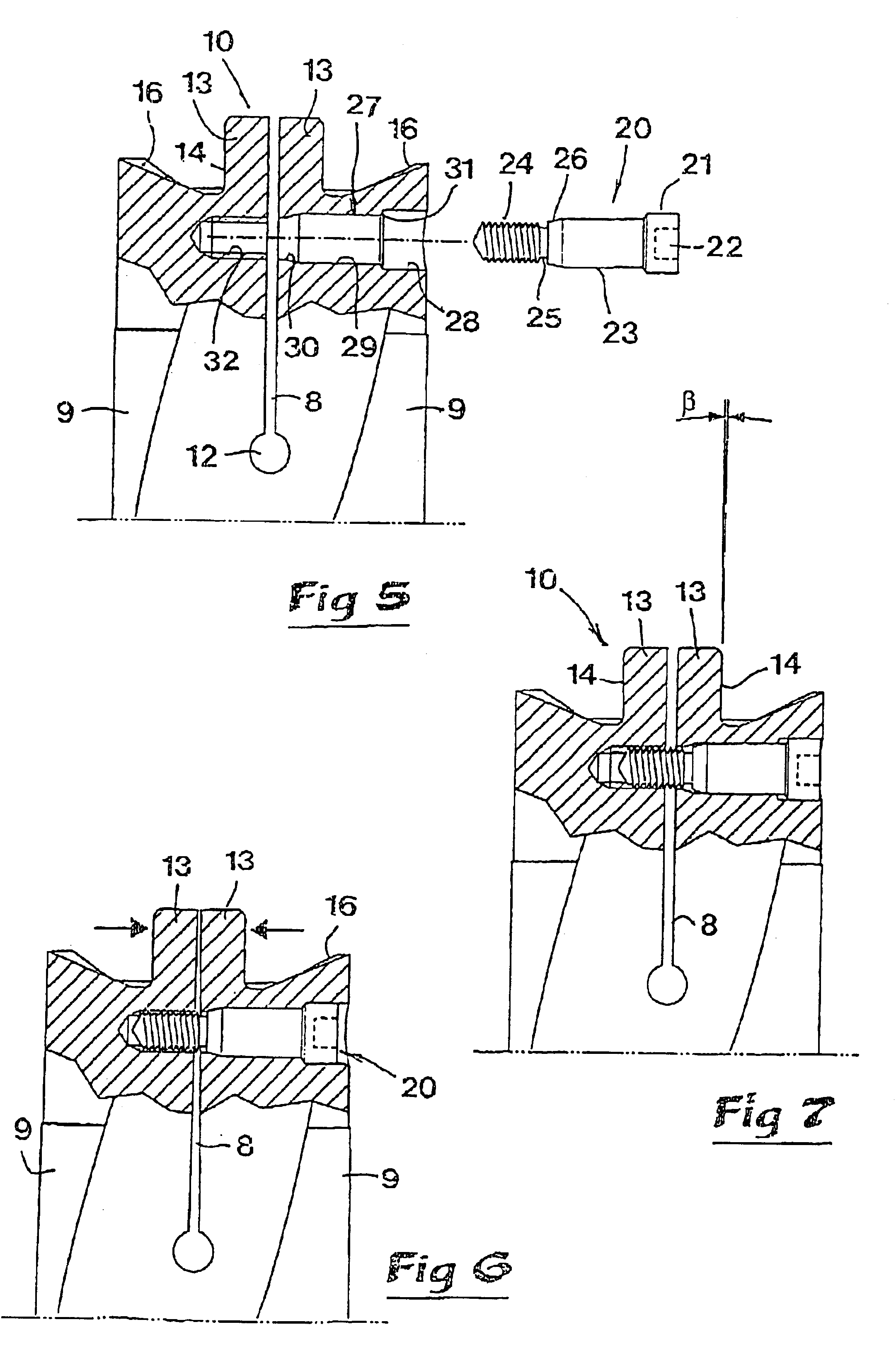
In FIGS. 1-7, a first embodiment of a rotatable, chip removing tool according to the invention is visualized, more precisely in the form of a drill, which in the usual manner includes a holder part, in its entirety designated 1, as well as a replaceable cutting part or loose top 2. The holder part is formed with a rear, substantially cylindrical part 3, which is mountable in a machine, e.g. a multi-operational machine, as well as a thinner shank 4 having two helicoidal, cross-section-wise curved chip channels 5. The front end of the loose top 2 is formed with cutting inserts or cutting edges, which are partly outlined at 6 in FIG. 3. Generally, the loose top 2 is of a circular external contour shape having a diameter that is somewhat larger than the diameter of the shank 4. However, in the loose top, concavely curved limiting surfaces 7 are formed that connect with the curved shape of the chip channels 5.

The loose top 2 is entirely or partly manufactured from a hard, wear-resistant ...


PUM

PropertyMeasurementUnit
cone angleaaaaaaaaaa

Abstract

A rotatable tool for chip removing machining having a rotatable holder part and a cutting part that is detachably connected to a front end of the holder part. In a front end portion of the holder part, a forwardly open slot is formed, which separates two elastically flexible branches of the holder part. For clamping of the cutting part on the holder part, a male / female coupling is arranged, which comprises a centrical, male-like pin on one of the parts and a corresponding seat in the other part. Disposed on the holder part radially outside of the male / female coupling are thrust load carrying support surfaces, which surfaces are at least partially conical and are engaged by corresponding support surfaces of the cutting part. During a cutting operation, axial thrust loads transmitted to the axial thrust support surfaces cause the branches to be pressed in a direction intensifying the radial contact between the pin and the seat.

Description

This application claims priority under 35 U.S.C. .sctn.119 and / or 365 to Patent Application Serial No. 0103555-9 filed in Sweden on Oct. 25, 2001, the entire content of which is hereby incorporated by reference.This invention relates to a rotatable tool intended for chip removing or chip forming machining, comprising two portions, viz. a rotatable holder part mountable in a machine, and a cutting part that is detachably connected to a front end of the holder part, a forwardly open slot being formed in a front end portion of the holder part, which slot separates two or more elastically flexible or resilient branches.PRIOR ARTChip forming tools of the type that uses a holder part or basic body as well as a separate, replaceable cutting part may in practice be of highly varying shapes and may consist of, for instance, drilling tools, milling tools, such as shank-type cutters and slot cutters, respectively, thread cutters, etc. The holder part usually consists of a long narrow, cylindri...

Claims


Application Information

Patent Timeline
Patent Type & Authority Patents(United States)
IPC IPC(8): B23B51/02
CPCB23B51/02B23B2205/02B23B2251/02Y10T408/9098Y10T408/9097Y10T408/907Y10S408/713
Inventor LINDBLOM, STEFAN
Owner SANDVIK INTELLECTUAL PROPERTY AB
Why Eureka
Try Eureka