

Milling Tool
a technology of milling tool and tool head, which is applied in the direction of manufacturing tools, gear teeth, manufacturing apparatus, etc., can solve the problems of adversely affecting the machining precision of workpieces, and achieve the effects of good machining, high positioning reliability, and high dimensional accuracy of tools
- Summary
- Abstract
- Description
- Claims
- Application Information
AI Technical Summary
Benefits of technology
Problems solved by technology
Method used
Image

Examples
second embodiment
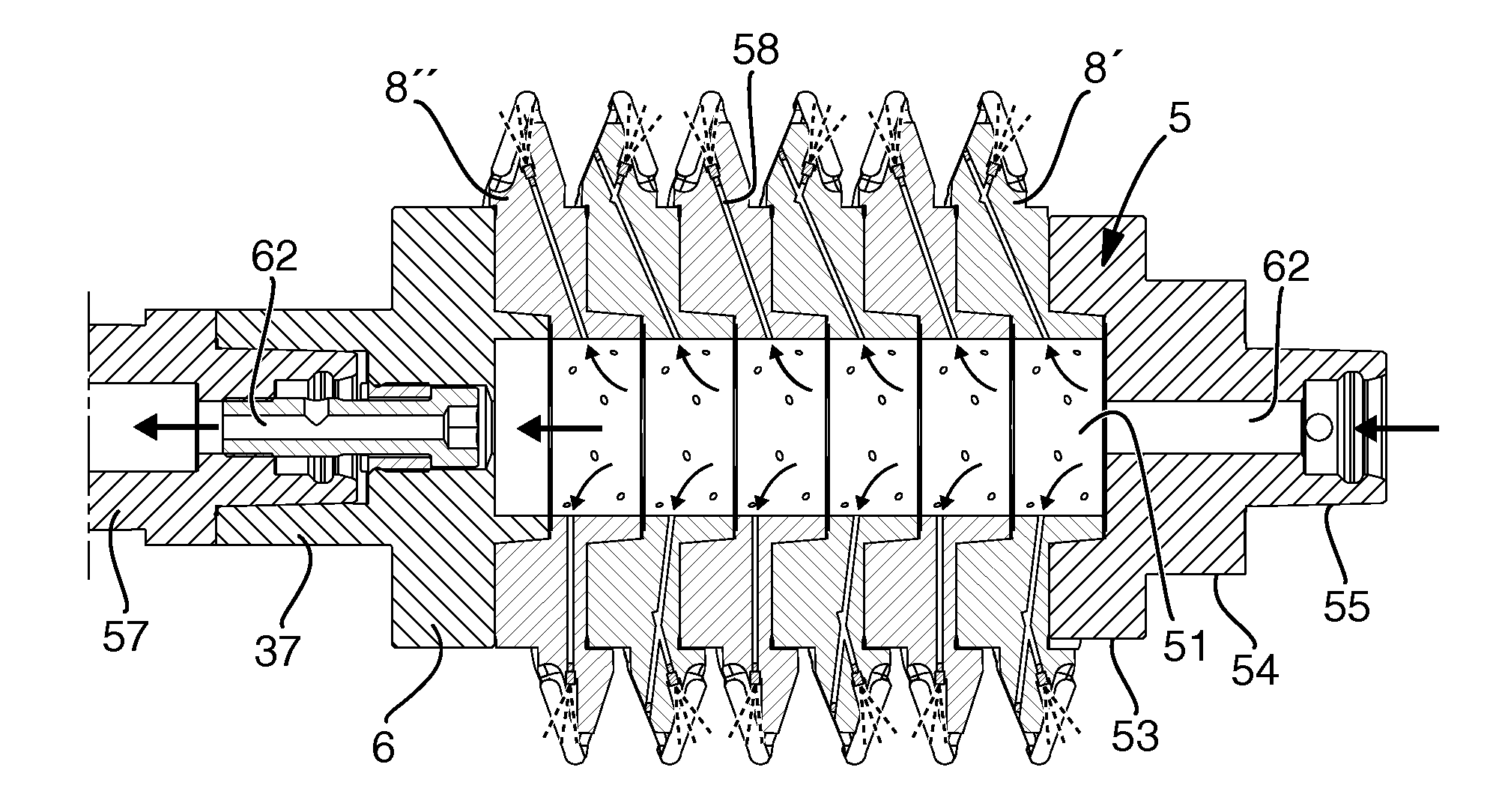
[0069]In the shown, second embodiment, each branch duct 58 is formed as two straight subducts. The inner subduct extends from the central hole 51 outward through the hub part 11 between the screw holes 35 and the bores 27 toward the cam 12 and mouths at a point in the chip channel 21. This point is selected in such a way that it is possible to drill straight in from said point toward the central hole without intersecting any threaded hole 35 or bore 27. The outer part of the inner subduct 59 is plugged up for the prevention of leakage of the cooling medium to be used.
[0070]The other, outer subduct 60 extends straight from the position in chip space 21 in question where supply of cooling medium is desired to the cutting process inward toward a suitable point of the inner branch duct 59. Thus, it is possible to drill also the outer branch duct 60 straight and in one step.
[0071]Together, the two subducts 59, 60 form a connection duct in the form of a branch duct 58 from the central hol...
first embodiment
[0094]In FIG. 10, two adjacent segments of a milling tool are shown in an assembled state. T designates the thickness of the individual segment, such as this is determined by the axial distance between the end surfaces 13 and 14. This measure coincides moreover with the pitch of the cam 12. The depth of the recess 37 is designated L1, while the axial length of the male member 36 is designated L2. L1 should amount to at least 30% and at most 80% of T. Preferably, L1 is within the interval of 50-70% of T. L1 is smaller than L2. When the male member 36 engages the appurtenant recess in the assembled state of the tool, there is a gap 44 between the free end 43 of the male member and the bottom of the recess. In other words, the male member does not touch the bottom in the recess. In this way, it is advantageously guaranteed that the desired axial end position according to the invention, in which the plane-parallel surfaces of two bordering segments abut against each other, is reached w...
PUM
| Property | Measurement | Unit |
|---|---|---|
| angle of convergence | aaaaa | aaaaa |
| angle of convergence | aaaaa | aaaaa |
| angle of convergence | aaaaa | aaaaa |
Abstract
Description
Claims
Application Information