Modular ceramic oxygen system

Active Publication Date: 2004-08-31
COBHAM MISSION SYST DAVENPORT LSS INC
View PDF17 Cites 9 Cited by
  • Summary
  • Abstract
  • Description
  • Claims
  • Application Information

AI Technical Summary

Problems solved by technology

A significant problem arises when the product flow rate from the system is turned down.
This auxiliary heat input has no functional value, save for maintaining temperature, and a significant fraction of it bercomes an unrecoverable loss due to conduction through the furnace walls and other losses.
Stated simply, a single furnace enclosure properly sized for one product flow rate

Method used


Image

  • Modular ceramic oxygen system
  • Modular ceramic oxygen system
  • Modular ceramic oxygen system

Examples


Embodiment Construction

So that the manner in which the above recited features, advantages, and objects of the present invention are attained can be understood in detail, more particular description of the invention, briefly summarized above, may be had by reference to the embodiment thereof that is illustrated in the appended drawings. In all the drawings, identical numbers represent the same elements.

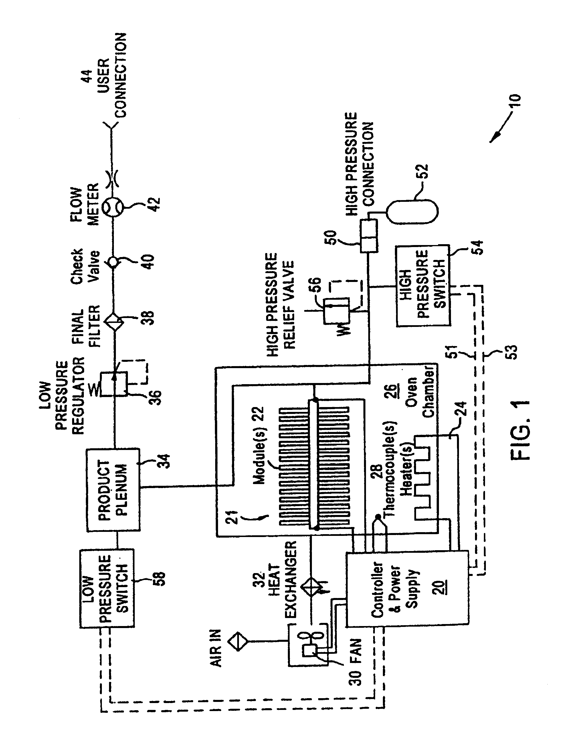
U.S. Pat. No. 5,985,113 issued on Nov. 16, 1999, U.S. Pat. No. 5,871,624 issued on Feb. 16, 1999 and U.S. Pat. No. 6,194,335 issued on Feb. 27, 2001, all of which are incorporated herein in their entirety and assigned to the instant assignee, teach how an electrochemical oxygen generating device can be manufactured that not only generates oxygen, but can be used to deliver the oxygen gas at pressures exceeding 2000 psig. It should be understood that terms such as "left" and "right" as used herein are to be construed in the relative sense and that the present invention is usable in any orientation.
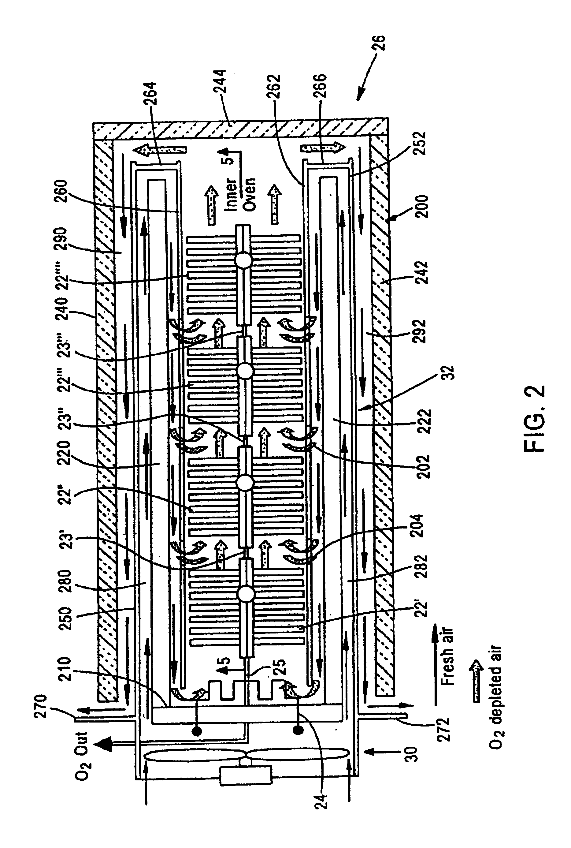
FIG. 1 illu...


PUM

PropertyMeasurementUnit
Heataaaaaaaaaa
Thermal conductivityaaaaaaaaaa

Abstract

An oven insert (110) for a gas generating system of the type that includes heating elements, heat exchanger, a gas generating module (22), an air inlet, and a product gas outlet, includes a furnace enclosure member formed with a plurality of interior chambers. The interior chambers (112) are adapted for holding at least one gas generating module (22). The interior chambers (112) each have an opening (122) formed an exterior face (124) of the furnace enclosure member (110). The openings are spaced along a central axis (126) of the face (124) of the furnace enclosure member (110).

Description

BACKGROUND OF INVENTION1. Technical FieldThe invention relates to the field of gas separation devices. More specifically, devices that use an electrochemical process to separate one gas (oxygen for example) from a mixture of gasses (air for example).2. Background ArtIn one embodiment of a gas generating system, a solid-state process is used to separate oxygen from atmospheric air for medical use. Such a device is called a ceramic oxygen generating system or COGS. The ceramic electrolyte used in the oxygen separation process must be maintained at a temperature of approximately 600A.degree. C. or higher for the ionic transport mechanism to operate efficiently. In addition, a fairly uniform temperature distribution with the separation furnace is essential to proper and efficient system operation.A significant problem arises when the product flow rate from the system is turned down. For any given operating temperature, the heat dissipated by the separation modules is roughly proportiona...

Claims


Application Information

Patent Timeline
IPC IPC(8): B01J7/00C25B9/00H01M8/10B01DB01D53/32C01B13/02
CPCC01B13/0251F27D1/04C01B2210/0046
Inventor SEHLIN, SCOTT R.PHILLIS, TIMOTHY C.
Owner COBHAM MISSION SYST DAVENPORT LSS INC
Why Eureka
Try Eureka