
Flow Control Valve, Typically a Check Valve for Cryogenic, Oxygen and High Pressure Air Valves

a flow control valve and check valve technology, applied in the direction of lift valves, valve details, functional valve types, etc., can solve the problems of loss of plants, severe injury and death, and all materials are flammable, and will burn actively

Active Publication Date: 2010-03-04
OXYCHECK
View PDF20 Cites 9 Cited by
  • Summary
  • Abstract
  • Description
  • Claims
  • Application Information

AI Technical Summary

Benefits of technology

"The invention is a flow control valve for oxygen systems that has a seat, a ball, a biasing means, and a ball retainer. The ball retainer can capture the ball and hold it in a closed position to prevent gas flow. The materials used for the valve are typically brass or copper based alloys. The hardness of the ball is preferably above 7 on the Mohs hardness scale. The biasing means is typically a spring that prevents the ball retainer from moving more than a certain distance. A lock device can hold the spring retainer in a desired position. The valve has a low cracking pressure."

Problems solved by technology

If oxygen is not properly controlled or used with equipment not specifically designed for oxygen, then accidents resulting in system failure and / or loss of plant, severe injury and death may occur.
As a result, almost all materials are flammable and will burn actively at high temperatures in the presence of oxygen.
Contaminants in oxygen systems are especially prone to ignite adjacent metallic and non-metallic materials and therefore greatly increase the potential for fire.
Oxygen flowing at high speed through a valve or piping systems can also propel contaminants or particles with such force that friction or impact between the particles and / or system components can raise the temperature to ignition point of the contaminants, particles, or metallic system components, resulting in a major incident.
However, due to economic constraints and in order to achieve a non-leaking oxygen system, resilient sealing materials typically made of plastics, synthetic rubbers or some soft metals are often used.
Unfortunately, these materials are less resistant to ignition than other metallic materials.
Accordingly, materials with more favorable ignition and burning characteristics often result in leakages.

Method used


Image

  • Flow Control Valve, Typically a Check Valve for Cryogenic, Oxygen and High Pressure Air Valves
  • Flow Control Valve, Typically a Check Valve for Cryogenic, Oxygen and High Pressure Air Valves
  • Flow Control Valve, Typically a Check Valve for Cryogenic, Oxygen and High Pressure Air Valves

Examples


Embodiment Construction

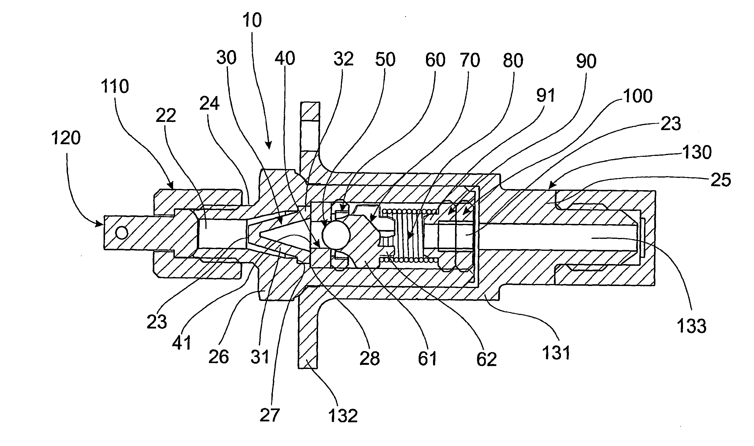
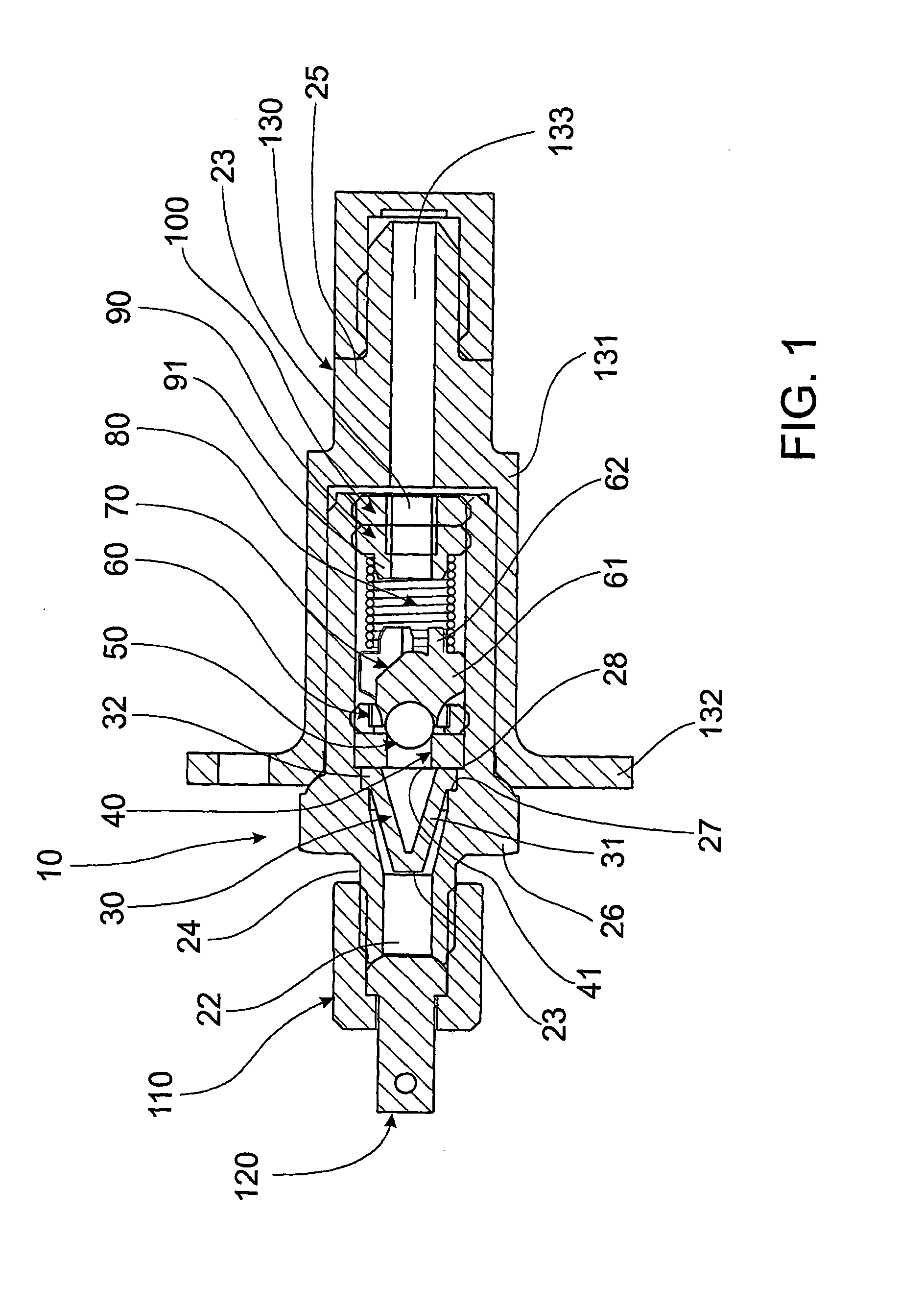
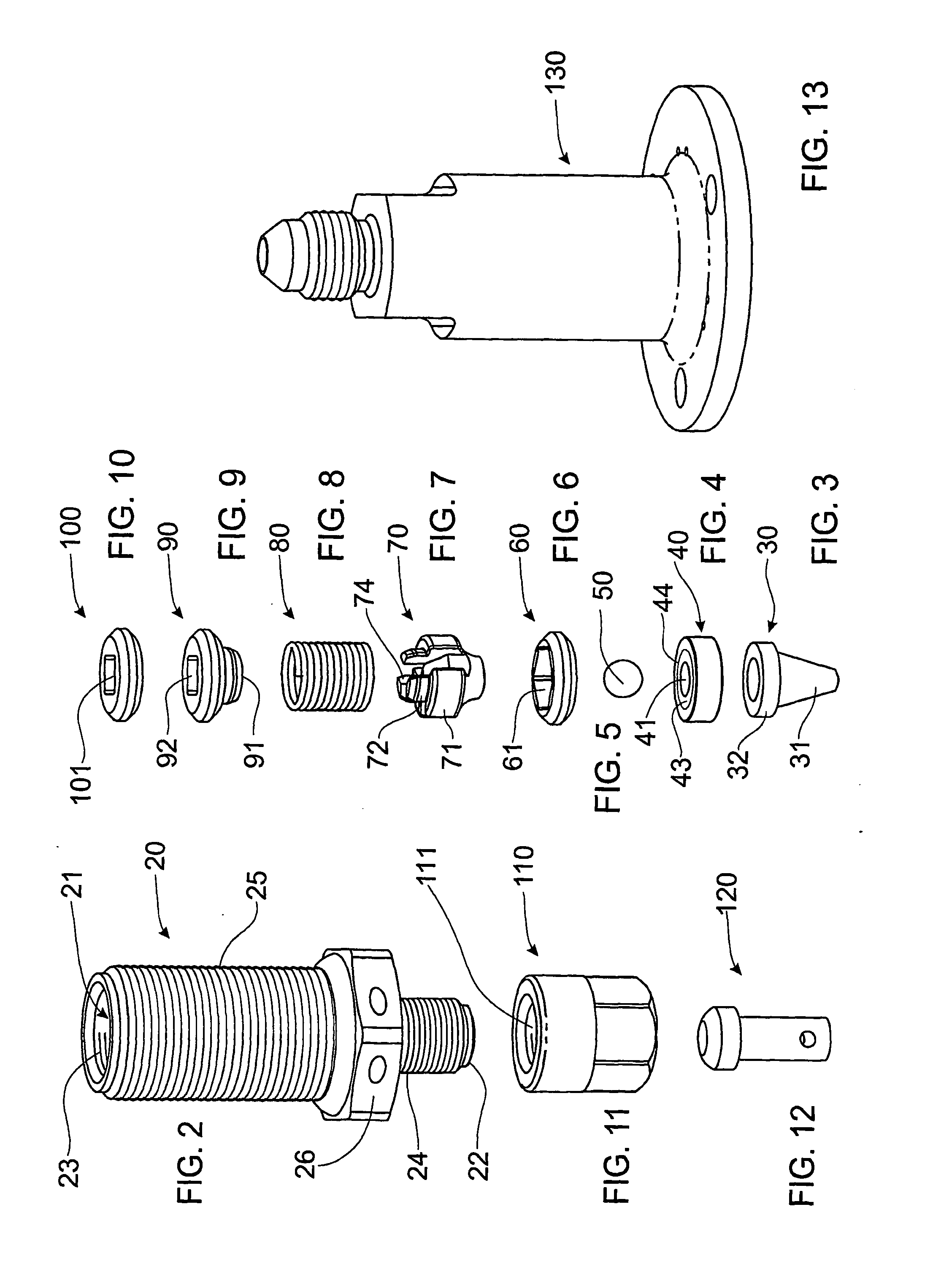
[0047]FIG. 1, 14 and 15 shows a flow control valve 10 for use in a high pressure oxygen system. In particular, the flow control valve 10 shown in FIGS. 1, 14 and 15 is for use with aircraft so that oxygen cylinders that are carried within the aircraft can be filled quickly, easily and safely. The flow control valve 10 includes a valve body 20, filter 30, seat 40, ball 50, seat retainer 60, ball retainer 70, spring 80, spring retainer 90, lock device 100, dust cap 110, dust cap plug 120 and housing 130.

[0048]The valve body 20, shown in FIG. 2, has a central passageway 21 that allows oxygen to flow from an inlet 22 to an outlet 23 through the valve body 20. An inlet stem 24 is located adjacent the inlet 22 whilst an outlet stem 25 is located adjacent the outlet 23. A hexagonal head 26 separates the inlet stem 24 from the outlet stem 25. Both the inlet stem 24 and outlet stem 25 have an external thread. The outlet stem 25 also has an internal thread that extends along the passageway 23...


PUM


Abstract

A flow control valve for use in oxygen systems. The flow control valve has a body within an inlet and an outlet. A seat is located within the body and a ball retainer is located within the body. The ball retainer is able to capture a ball. The flow control valve also has biasing means connected to the ball retainer. Furthermore, the biasing means is movable between a flow and a non-flow position. The ball retainer is in a closed position when the ball, captured by the ball retainer, engages the seat to prevent gas flowing through the seat.

Description

FIELD OF THE INVENTION[0001]THIS INVENTION relates to a flow control valve. In particular, the invention relates to a flow control valve for use in oxygen-enriched environments and will therefore be described in this context. Oxygen-enriched environments include, but are not limited to, systems using low and high-pressure pure oxygen, high-pressure air and oxygen / nitrogen mixes with higher oxygen concentrations than standard temperature and pressure breathing air. However, it will be appreciated that the flow control valve may be used for other applications.BACKGROUND OF THE INVENTION[0002]Oxygen and high-pressure air valves are used in many applications including oxygen tanks, SCUBA systems, filling stations, space capsules, in-home liquid oxygen tank systems, fuel pipe oxygen systems, aeroplane pilots' breathing apparatus, hospital breathing apparatus, steel, chemical and cold gasification plants, oxygen powered engines or any other associated processes. If oxygen is not properly ...

Claims


Application Information

Patent Timeline
Patent Type & Authority Applications(United States)
IPC IPC(8): F16K15/04
CPCF16K15/044F16K25/005F16K15/048Y10T137/7927Y10T137/7928
Inventor NELSON, PETER JAMESDE WITT, JOHN ROBERTSTEINBERG, THEODORE AARON
Owner OXYCHECK
Learn More