

Mechanism for correcting unbalance of a rotor
a technology of unbalance and rotor, which is applied in the field of mechanical equipment for correcting unbalance of rotor, can solve the problems of deterioration of image quality recorded on printing plate, time-consuming, adversely affecting processing efficiency,
- Summary
- Abstract
- Description
- Claims
- Application Information
AI Technical Summary
Benefits of technology
Problems solved by technology
Method used
Image

Examples
Embodiment Construction
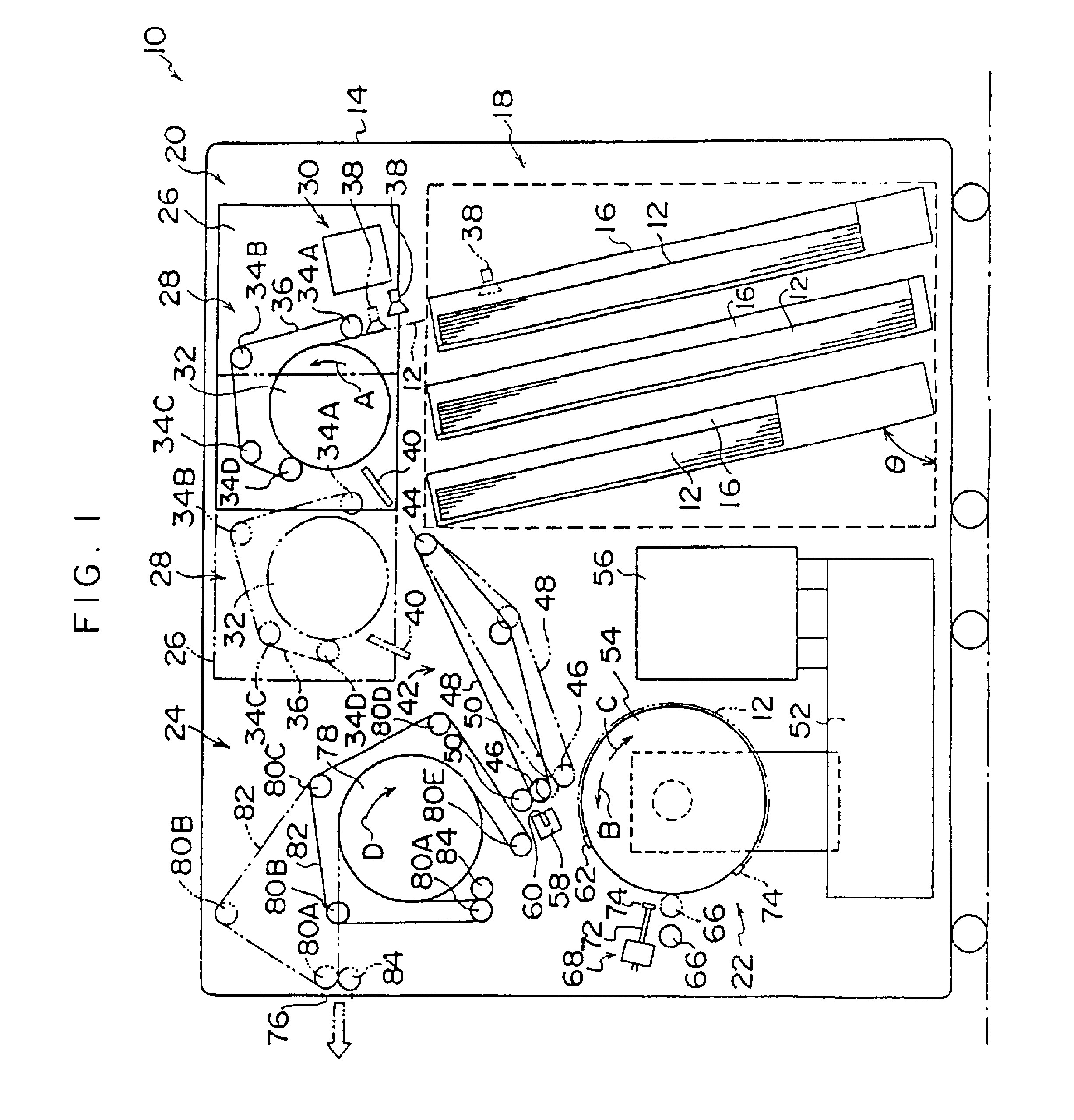
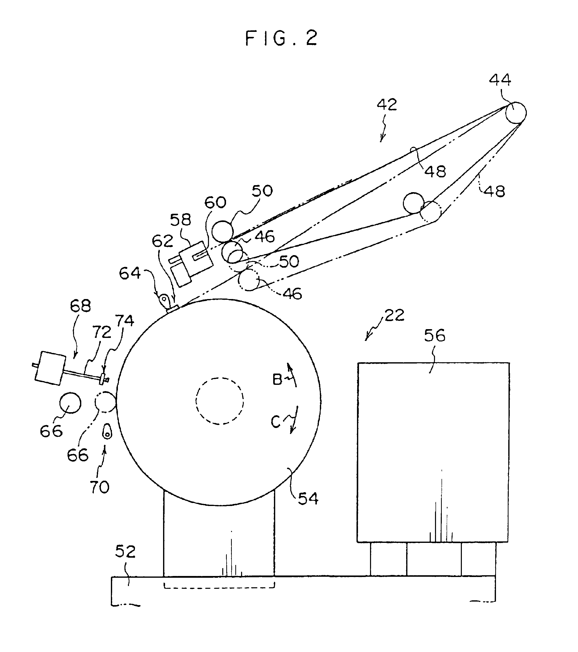
An embodiment of the present invention will be described with reference to the drawings. FIG. 1 shows a schematic configuration of an image exposure apparatus 10 according to the present invention. The image exposure apparatus 10 irradiates a sheet member (hereinafter, "printing plate 12") with a light beam modulated on the basis of image data to thereby scan-expose the printing plate 12. The printing plate 12 is a photosensitive planographic printing plate (having, for example, a thickness t of 0.3.times.10.sup.-3 m and a density c of 2.7.times.10.sup.3 kg / m.sup.3) comprising a thin, rectangular plate-like support (e.g., aluminum) having disposed thereon a photosensitive layer. After the printing plate 12 is image-exposed in the image exposure apparatus 10, the printing plate 12 is developed and processed by an automatic developing apparatus (not illustrated). The minimum size of the printing plate 12 to which the present embodiment is applied is 500.times.500.times.0.2 mm, and the...
PUM
| Property | Measurement | Unit |
|---|---|---|
| radius | aaaaa | aaaaa |
| radius | aaaaa | aaaaa |
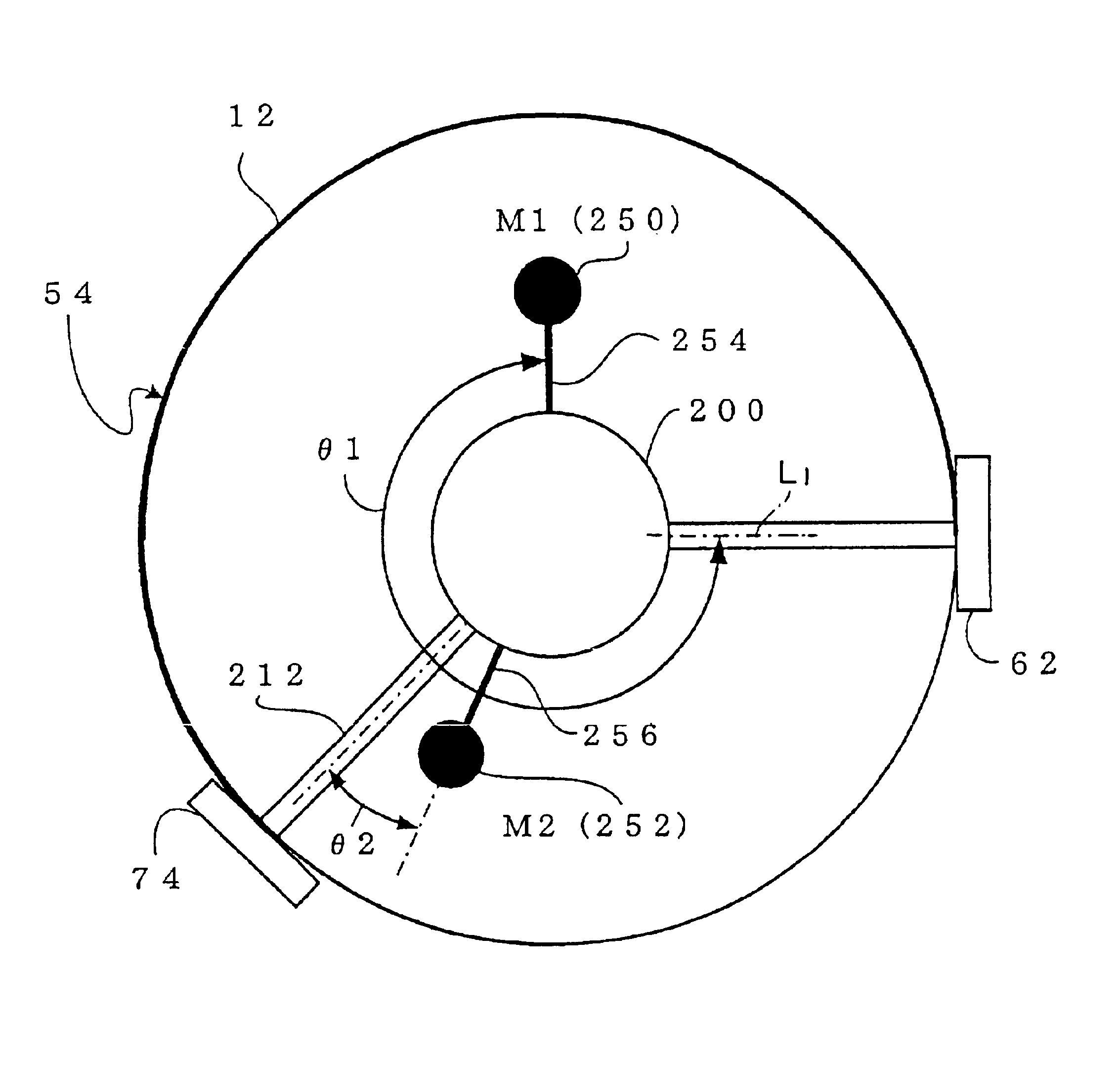
| angle θ1 | aaaaa | aaaaa |
Abstract
Description
Claims
Application Information