
Spin balanced crank assembly

a crank and clutch technology, applied in the direction of machines/engines, mechanical equipment, manufacturing tools, etc., can solve the problems of shortening the operating life of certain engine parts, wasting energy, and affecting the stability of the crank shaft,

Inactive Publication Date: 2012-02-16
WILSON AUDIO SPECIALTIES
View PDF19 Cites 4 Cited by
  • Summary
  • Abstract
  • Description
  • Claims
  • Application Information

AI Technical Summary

Benefits of technology

[0017]It is an object of the present invention to provide an improved system and method for correcting the unbalance in ATV and snowmobile engines.
[0018]According to one aspect of the present invention, at least one mass is added to the crankshaft assembly without opening the engine to thereby correct unbalance in the engine.
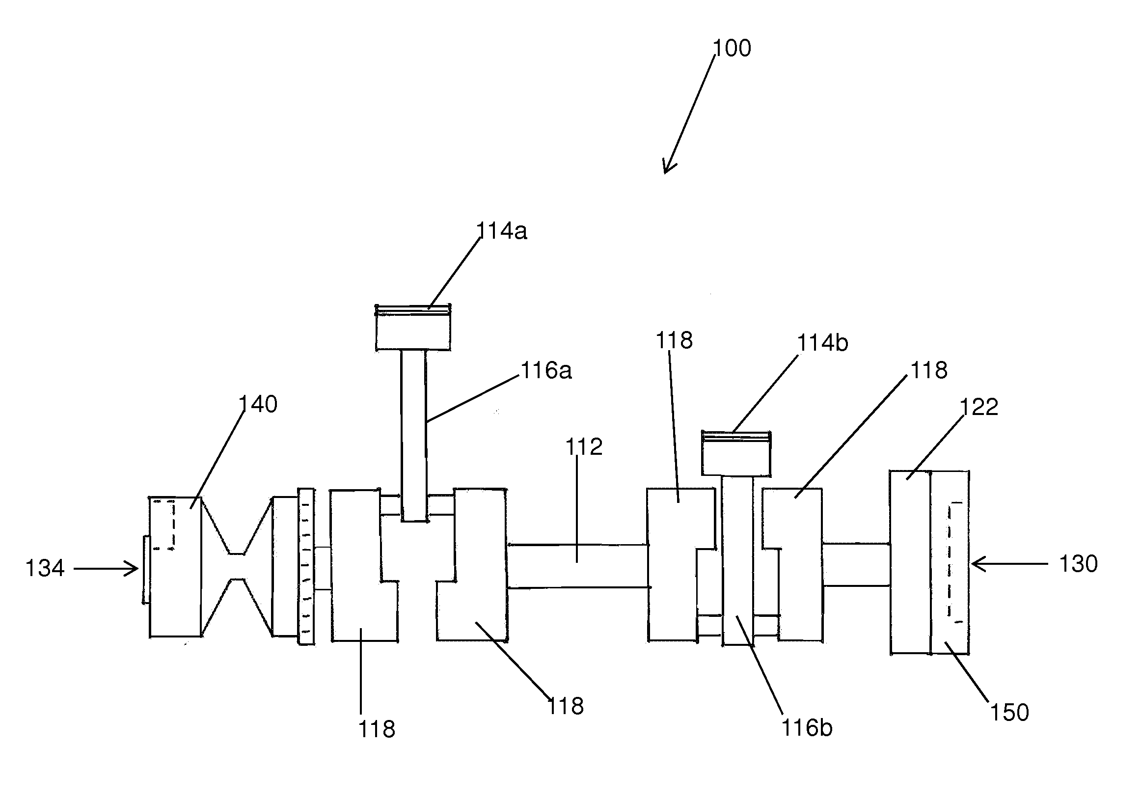
[0019]According to another aspect of the present invention, a first mass is added to the PTO side of an engine and a second mass is attached to the magneto side of an engine without opening the engine case assembly to thereby achieve a two-plane balance of the crank assembly.
[0020]According to another aspect of the present invention, a two-plane spin balanced crank assembly may be provided without adding weight to or subtracting weight from the crankshaft.

Problems solved by technology

If they do not, the rotating assembly will generate friction and vibration, which wastes energy and will shorten the operating life of certain engine parts, e.g. bearings.
Unbalance may occur when the center-of-gravity of a rotating object is not aligned with its center-of-rotation.
This unbalance misaligns the center of gravity and bearing journals of the engine rotating assembly, causing vibration and wear.
In general, unbalance can occur at any lateral (axial) position along the rotating assembly and with any magnitude.
This unbalance is a combination of static unbalance and couple unbalance and is called dynamic unbalance.
The couple unbalance component only appears when the object is rotated; so measuring dynamic unbalance requires rotating the object.
The larger and heavier the object and the faster it rotates, the greater the forces generated by any unbalance that exist.
Also, the further the weight creating the unbalance is located from the center of gravity, the greater its effect on the rotating part as it spins.
One problem with balancing two-stroke and four-stroke engines, such as those used in snowmobiles and ATVs, is that they typically comprise multiple separate pieces pressed together, making it extremely difficult, if not impossible, to put it on a hard bearing balancer without substantial support to hold the rods and pistons in place.
One downside of traditional methods of balancing two-stroke or four-stroke engines such as those used in snowmobiles and ATVs, however, is that it is both time and labor intensive and can take up to 25 hours or more to complete, which makes balancing these engines very costly to the consumer.
The alternative for the consumer, however, is to use the snowmobile or ATV without correcting the unbalance in its engine.
There are several disadvantages of not correcting an unbalanced engine such as a snowmobile or ATV engine.
These disadvantages include engine movement even when high density rubber motor mounts are used.
Also, engine vibration may be transmitted to the handlebars and other parts of the snowmobile or ATV causing the rider to become fatigued.
Although handlebar vibration dampeners may be mounted to the snowmobile or ATV to reduce the effects of an unbalanced engine, the vibrations still unnecessarily increase the wear on the snowmobile's or ATV's mechanical parts.
For example, vibration can cause crank bearing failure, which may cause excessive crank run out, which in turn may result in the pistons seizing.
Another disadvantage of not correcting unbalance in two-stroke and four-stroke engines such as those used in a snowmobile or ATV is that vibration caused by the unbalanced engine may result in excessive heat build-up that may transfer to other parts or materials in contact with the engine.
For example, excessive heat may cause the clutch belt to weaken and break, leading to failure of the clutch bushing, thus destroying the clutch.
Moreover, vibration caused by an unbalanced engine may fatigue the entire crank assembly, which can cause cylinders to crack, pistons to break off at the rod connection, and even cause clutches to break off at the power take off (PTO) end of the engine.
However, this still requires disassembling the engine, removing the original bearing, and replacing it with the aftermarket bearing.
This process may still be time consuming and expensive for the consumer; and, although this may increase the life of the crank assembly, it does not decrease the unbalance of the engine and vibrations associated therewith.
Again, this additional bearing may increase the life of the crank assembly, but it does not correct unbalance in an engine.
However, these methods of reducing vibration in a snowmobile or ATV due to an unbalanced engine have had minimal success.

Method used


Image

  • Spin balanced crank assembly
  • Spin balanced crank assembly
  • Spin balanced crank assembly

Examples


Embodiment Construction

[0042]The drawings will now be discussed in reference to the numerals provided therein so as to enable one skilled in the art to practice the present invention. The drawings and descriptions are exemplary of various aspects of the invention and are not intended to narrow the scope of the appended claims.

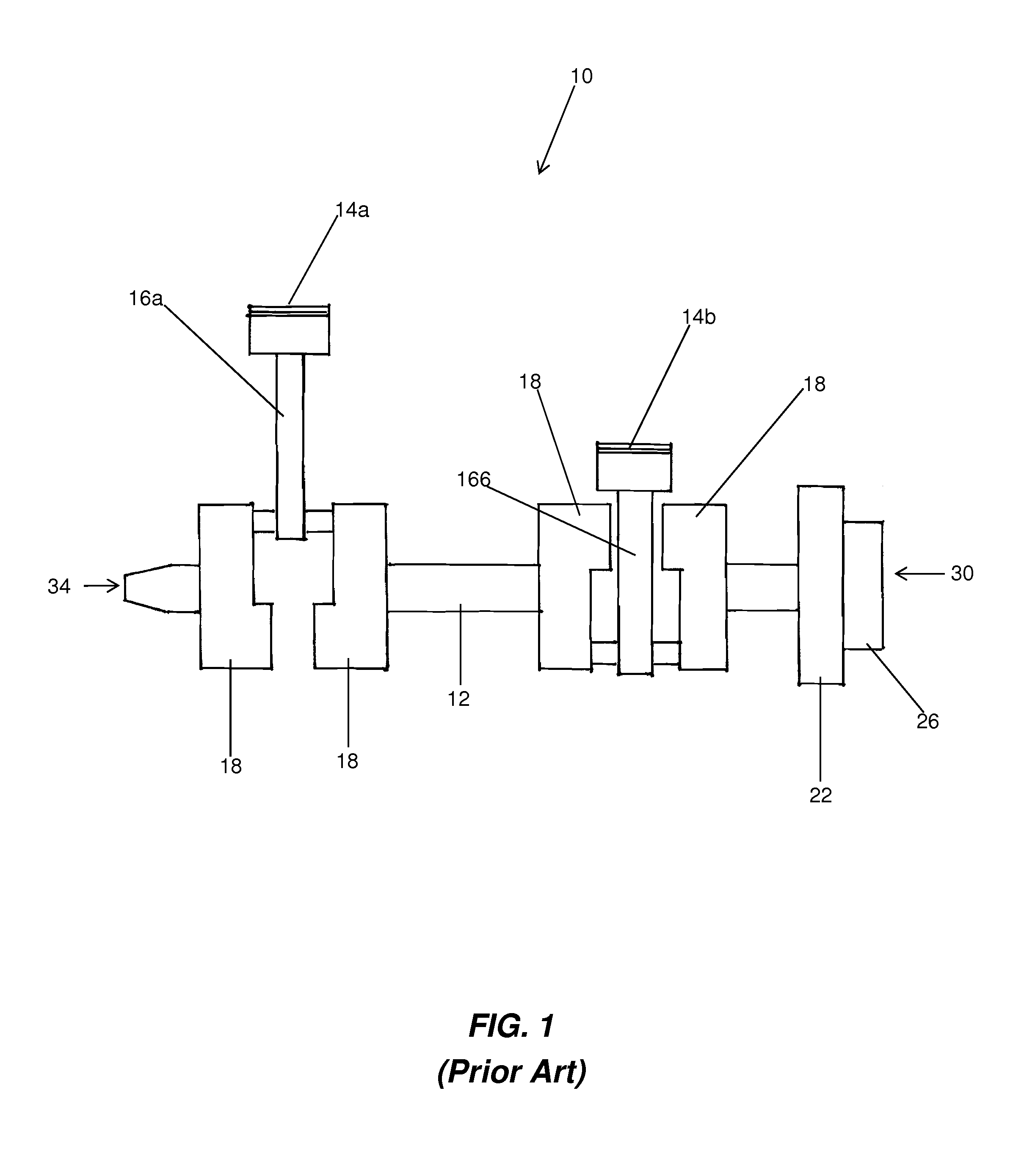
[0043]Turning to FIG. 1, there is shown a side view of a two-stroke or four-stroke crank assembly, generally indicated at 10, of a two cylinder motor according to principles of the prior art. The rotating assembly (including the crankshaft (often referred to simply as the crank), connecting rods and pistons) of a snowmobile motor is shown. The present invention is particularly suited to the engines of snowmobiles, ATVs and the like as these engines have multi-piece cranks which are pressed together with the connecting rods and pistons permanently installed on the crank. As compared to automobile engines, these rotating assemblies are more difficult to balance in a conventional manner...


PUM

PropertyMeasurementUnit
specific angleaaaaaaaaaa
massaaaaaaaaaa
angleaaaaaaaaaa

Abstract

A spin balanced crank assembly for two-stroke and four-stroke engines, such as those used in snowmobiles and ATVs, is provided. The crank assembly may achieve an overall two-plane balance engine by adding two additional masses to opposing sides of the crank assembly. The additional masses are each unbalanced to a desired amount and angle in order to offset unbalance in the engine and obtain a balanced assembly. The amount of weight to be added or subtracted may be attached to the masses may be determined by the size and engine from which the crank assembly is a part of because the angle of unbalance of the crank assembly is know beforehand. Additionally, methods for spin balancing two-stroke and four-stroke engines are provided, wherein the method comprises balancing the engine without disassembling the crank.

Description

PRIORITY[0001]The present application claims the benefit of U.S. Provisional Patent Application Ser. No. 61 / 406,894, filed Oct. 26, 2010, which is incorporated herein by reference in its entirety.THE FIELD OF THE INVENTION[0002]The present invention relates to a spin balanced crank and clutch assembly and methods of producing the same. More specifically, the present invention relates to a spin balanced clutch, rotor and crank assembly that is particularly applicable for use in the two-stroke and four-stroke engines used in snowmobiles and all-terrain vehicles (ATVs), and methods of spin balancing said assembly.BACKGROUND[0003]Reciprocating piston engines have a crankshaft that rotates at high speed and pistons and connecting rods that oscillate up and down with every revolution of the crank, all of which generates forces inside the engine. These parts are referred to as the engine's rotating assembly. Ideally, the sum of these centrifugal and translational forces equals zero. If the...

Claims


Application Information

Patent Timeline
Patent Type & Authority Applications(United States)
IPC IPC(8): F16F15/26B23P11/00
CPCF16F15/26F16C3/20Y10T29/49231
Inventor PERKINS, JOSEPH M.
Owner WILSON AUDIO SPECIALTIES
Learn More