Toroidal continuously variable transmission

a technology of continuously variable transmission and toroidal shaft, which is applied in the direction of engine components, mechanical equipment, gears, etc., can solve the problems of achieve the effect of increasing the dimension and the weight of the entire continuously variable transmission and greatly reducing the strength of the discs

Active Publication Date: 2020-06-09
KAWASAKI JUKOGYO KK
View PDF18 Cites 0 Cited by
  • Summary
  • Abstract
  • Description
  • Claims
  • Application Information

AI Technical Summary

Benefits of technology

The present invention provides a toroidal continuously variable transmission that can correct unbalance of a disc without impairing the strength of the disc, while suppressing an increase in the size of the continuously variable transmission. An interposed member separate from the disc is used to balance adjust the disc and can be connected to the integrally rotating member so as to rotate together with the disc. The balance adjustment portion of the interposed member can be formed as a plurality of radial projections arranged at equal intervals in the circumferential direction, making it easy to perform a balance adjustment work operation.

Problems solved by technology

However, since high stress is applied to the entireties of the discs of the continuously variable transmission, when the discs are subjected to processing such as perforating even at the outer peripheral surfaces thereof, there is a possibility that the strength of the discs greatly decreases.

Method used


Image

  • Toroidal continuously variable transmission
  • Toroidal continuously variable transmission
  • Toroidal continuously variable transmission

Examples


Embodiment Construction

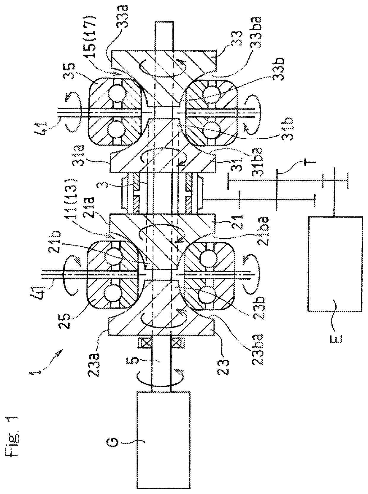
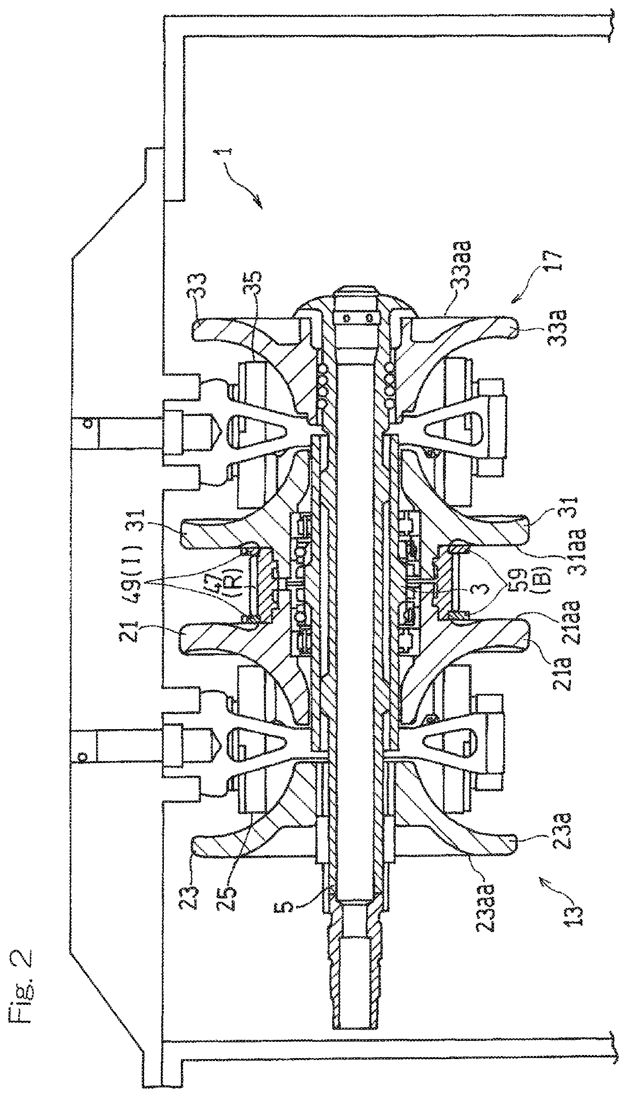
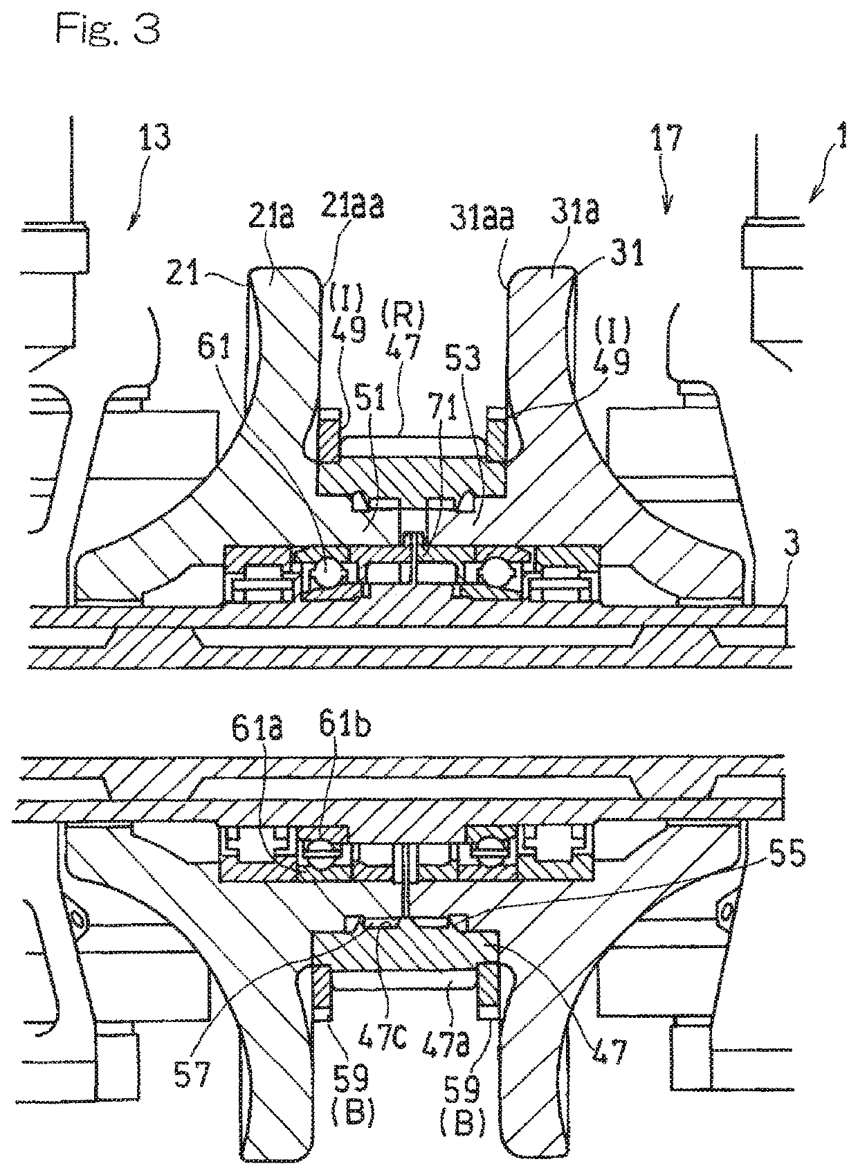
[0031]Hereinafter, embodiments of the present invention will be described with reference to the drawings. FIG. 1 is a longitudinal cross-sectional view schematically showing a toroidal continuously variable transmission (hereinafter, referred to simply as a “continuously variable transmission”) 1 according to a first embodiment of the present invention. The continuously variable transmission 1 is provided between an aircraft engine E that is a drive source and a generator G that is a load device driven by the engine E. The continuously variable transmission 1 transmits a driving force of the engine E to the generator G while keeping a rotation rate of the generator G constant. A constant frequency generator mainly includes the continuously variable transmission 1 and the generator G. In the present embodiment, a “radial direction” that is not particularly specified refers to a radial direction based on the axis of an input shaft 3 or output shaft 5, which will be described later.

[00...


PUM


Abstract

In a toroidal continuously variable transmission including at least one transmission unit including: an input disc and an output disc disposed coaxially; and a power roller tiltably interposed between the input disc and the output disc and configured to transmit a driving force from the input disc to the output disc, an integrally rotating member disposed so as to be spaced apart in an axial direction from at least one disc of the input disc and the output disc of each transmission unit and configured to rotate together with the at least one disc, and an annular interposed member provided between the at least one disc and the integrally rotating member and configured to rotate together with the at least one disc, are provided, and the interposed member is formed with a balance adjustment portion capable of adjusting weight balance in a circumferential direction.

Description

CROSS REFERENCE TO THE RELATED APPLICATION[0001]This application is a continuation application, under 35 U.S.C. § 111(a), of international application No. PCT / JP2015 / 061394, filed Apr. 13, 2015, which claims priority to Japanese patent application No. 2014-082827, filed Apr. 14, 2014, the disclosure of which are incorporated by reference in their entirety into this application.BACKGROUND OF THE INVENTION[0002](Field of the Invention)[0003]The present invention relates to a structure of a toroidal continuously variable transmission.[0004](Description of Related Art)[0005]As an electric power generating device for an aircraft, it is known to use a constant frequency generator (IDG) that operates while keeping a rotation rate (frequency) of a generator constant even when a rotation rate of an aircraft engine, which is a drive source, varies. As a transmission for keeping a rotation rate of the generator constant in the IDG, a toroidal continuously variable transmission has been propose...

Claims


Application Information

Patent Timeline
Patent Type & Authority Patents(United States)
IPC IPC(8): F16H15/38F16C19/54F16H37/02
CPCF16H15/38F16C19/541F16H37/021F16H2015/383F16C2361/00
Inventor ABE, AKIHITOTANAKA, KENICHIROIMAI, HIDEYUKIGOI, TATSUHIKOFUJII, ISAO
Owner KAWASAKI JUKOGYO KK
Why Eureka
Try Eureka