Cooling device with waterproof structure

a cooling device and waterproof technology, applied in the field of cooling devices, can solve the problems of deteriorating the maintenance performance of the heat exchanger, troublesome assembly steps of the cooling device, and difficulty in removing the heat exchanger

Inactive Publication Date: 2004-09-14
DENSO CORP
View PDF7 Cites 40 Cited by
  • Summary
  • Abstract
  • Description
  • Claims
  • Application Information

AI Technical Summary

Benefits of technology

According to the present invention, in a heat-exchanging device attached to a box to form an approximately sealed inner space within the box, a heat exchanger has therein a plurality of inside air passages through which inside air inside the box flows, and a plurality of outside air passages through which outside air outside the box flows. The inside air passages and the outside air passages are alternately adjacently arranged in the heat exchanger, and the heat exchanger is accommodated in a casing having an outer wall surface in which an outside air introduction port for introducing outside air into the outside air passages and an outside air discharge port for discharging outside air from the outside air passages are provided. In the heat-exchanging device, the heat exchanger is disposed in the casing to form a space having a predetermined distance between the heat exchanger and the outer wall surface, and the outside air passages are provided to communicate with the outside air discharge port through the space. Thus, even when rain water is introduced into the casing from the outside air discharge port, the rain water flows downwardly in the space between the heat exchanger and the outer wall surface of the casing, and therefore, it can prevent the rain water from being introduced into the heat exchanger.
Preferably, the casing has a drain passage communicating with the space, and the drain passage is provided at a position lower than a bottom surface of the heat exchanger. Therefore, rain water introduced into the space from the outside air discharge port can be readily discharged to a lower side of the heat exchanger.
The heat-exchanging device further includes a seal member through which a boundary part between the inside air passages and the outside air passages of the heat exchanger is water-tightly detachably attached to an attachment wall surface of the casing. Therefore, the heat exchanger can be readily detached from the casing after being assembled to the casing, and maintenance performance of the heat exchanger is improved. Further, because the boundary part of the heat exchanger is water-tightly attached to the attachment wall surface, seal performance of the heat-exchanging device between inside air side and outside air side can be improved.
More preferably, the inside air passages and the outside air passages are provided in such a manner that both the outermost air passages of the heat exchanger are two of the inside air passages. Therefore, wall parts defining the outermost inside air passages can be used as seal surfaces to be attached to the attachment wall surface of the casing through the seal member. Thus, waterproof performance of the heat-exchanging device can be further improved.

Problems solved by technology

Therefore, a potting process of resin material is necessary, and assembling steps of the cooling device become trouble.
Further, when once the waterproof process is performed, it is difficult to remove the heat exchanger from a casing of the cooling unit, and maintenance performance of the heat exchanger is deteriorated.

Method used


Image

  • Cooling device with waterproof structure
  • Cooling device with waterproof structure
  • Cooling device with waterproof structure

Examples


first embodiment

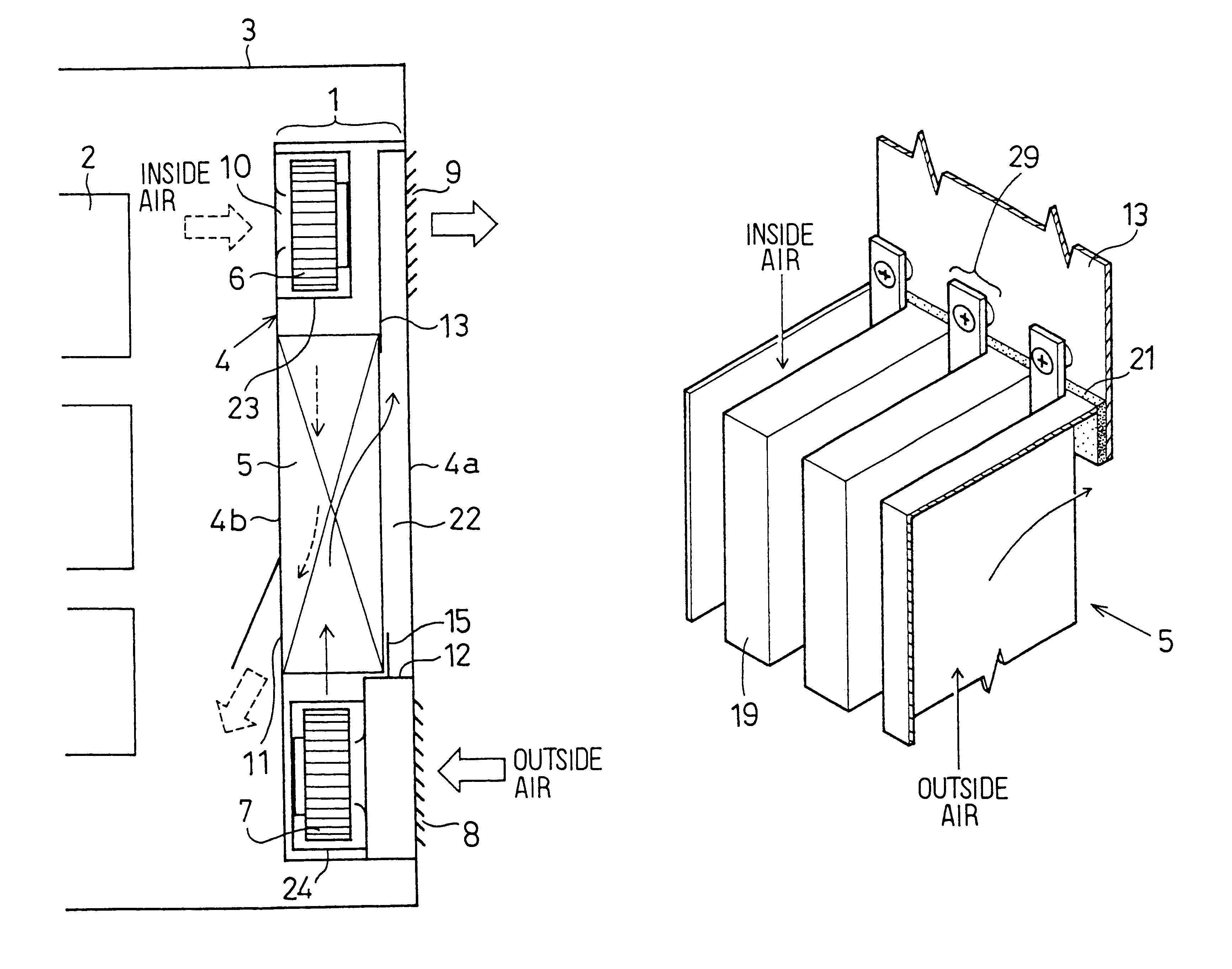
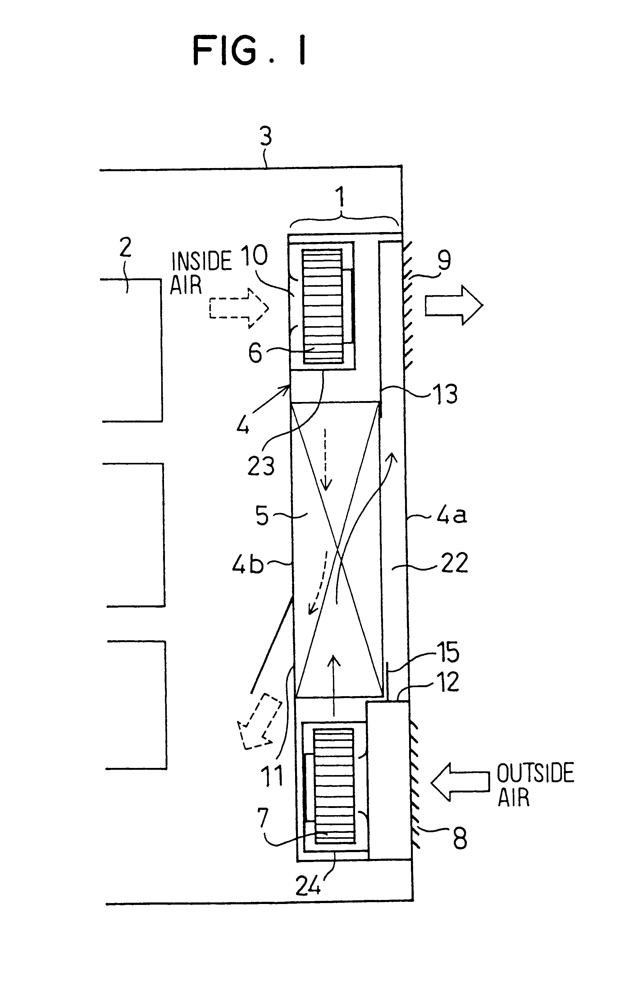
A first preferred embodiment will be now described. In the first embodiment, the present invention is typically applied to a cooling device 1. As shown in FIG. 1, the cooling device 1 is attached to a one side surface of a box (e.g., cabinet) 3 for accommodating a heat-generating member such as an electromagnetic member 2. The cooling device 1 is disposed to cool an inner part of the box 3 by performing a heat-exchange between inside air inside the box 3 and outside air outside the box 3. The box 3 defines an approximately sealed inner space when the cooling device 1 is attached to the box 3.

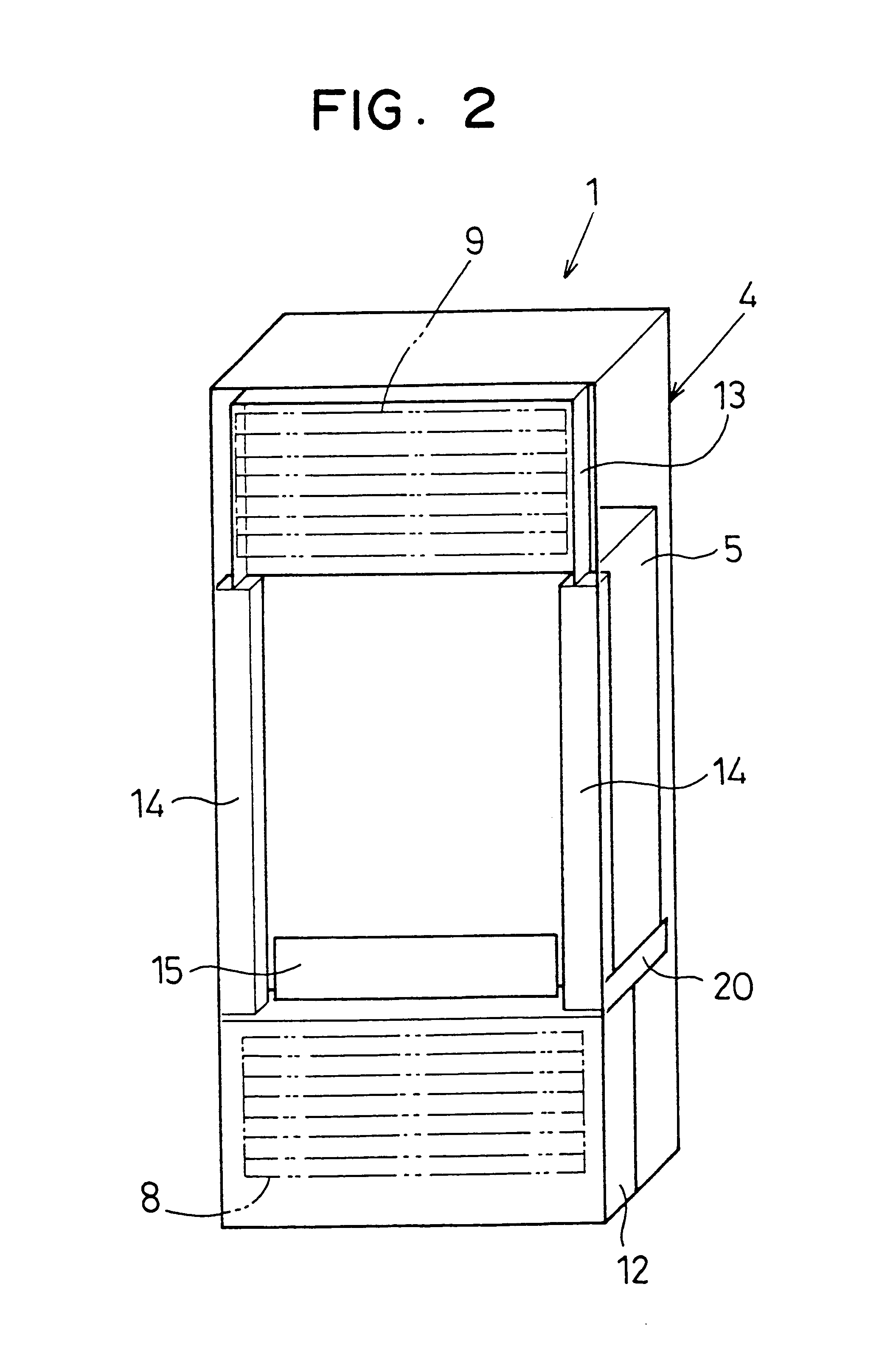
The cooling device 1 includes a casing 4, a heat exchanger 5, an inside air fan 6 and an outside air fan 7. The heat exchanger 5, the inside air fan 6 and the outside air fan 7 are disposed within the casing 4. The casing 4 has an outside side surface 4a in which an outside air introduction port 8 and an outside air discharge port 9 are formed, and an inside side surface 4b in which an inside ai...

second embodiment

A second preferred embodiment of the present invention will be described with reference to FIGS. 7-8C. In the second embodiment, as shown in FIG. 7, L-shaped members 26 each having a L-shaped cross section are disposed at the boundary angle parts between the inside air side and the outside air side of the heat exchanger 5, respectively. Specifically, the L-shaped members 26 are provided at the boundary angle part where an inlet opening surface of the inside air passages 16 and an outlet opening surface of the outside air passages 17 are crossed, and at the boundary angle part where an outlet opening surface of the inside air passages 16 and an inlet opening surface of the outside air passages 17 are crossed. Further, the packing 21 (see FIG. 4) is disposed to be inserted between the L-shaped member 26 and the flat surface of the casing 4, so that the waterproof performance is improved.

Here, on the inlet opening surface of the inside air passages 16, the plural inlet openings of the ...

third embodiment

the present invention will be now described with reference to FIGS. 9-10B. In the third embodiment, an attachment structure of the heat exchanger 5 is mainly described. As shown in FIG. 9, the rear surfaces of the plates 19 defining the inside air passages 16 or the outside air passages 17 are fixed to an inner wall surface of the casing 4 (e.g., partition wall 13) by a fitting member 29, so that a waterproof structure is formed. The fitting member 29 can be formed as shown in FIG. 10A, for example. As shown in FIG. 10A, the fitting member 29 includes a seal nut 30 disposed on an outer wall surface of the casing 4, a screw 31 disposed to be screwed into the seal nut 30, a fastening plate 32 through which a fastening force of the screw 31 is applied to a seal part (e.g., packing 21), and a bush 33 disposed between the fastening plate 32 and the casing 4. By setting a thickness of the bush 33, a fastening degree of the packing 21 can be controlled. Further, when the fastening plate 32...


PUM


Abstract

A cooling device for cooling an inner part of an approximately sealed box includes a casing and a heat exchanger disposed in the casing. Plural inside air passages through which air inside the box flows and plural outside air passages through which air outside the box flows are alternately adjacently arranged in the heat exchanger. In the cooling device, both outside air introduction port and outside air discharge port are provided in an outer side plate of the casing, and a drain space is provided between the heat exchanger and the outer side plate of the casing so that outside air passages communicate with the outside air discharge port through the drain space. Thus, even when rain water is introduced into the casing from the outside air discharge port, almost rain water flows downwardly through the drain space, and it can restrict rain water from being introduced into the heat exchanger.

Description

This application is related to and claims priority from Japanese Patent Application No. Hei. 11-276764 filed on Sep. 29, 1999, the contents of which are hereby incorporated by reference.1. Field of the InventionThe present invention generally relates to a cooling device for cooling an inner part of an approximately sealed box by a heat-exchange between air inside the box and air outside the box. More particularly, the present invention relates to a waterproof structure of a heat-exchanging device.2. Description of Related ArtIn a conventional cooling device for cooling a heat-generating member such as an electromagnetic member used within a sealed cabinet, a heat exchanger is disposed in the cabinet so that an inner part of the cabinet is cooled by performing a heat-exchange between air inside the cabinet and air outside the cabinet. However, because it is necessary to have a waterproof structure when the cabinet is disposed at an exterior space, an outer peripheral part of the heat...

Claims


Application Information

Patent Timeline
Patent Type & Authority Patents(United States)
IPC IPC(8): F28D9/00H05K7/20F25D1/00
CPCF28D9/0068H05K7/206
Inventor OKAMOTO, YOSHIYUKIKAWAGUCHI, KIYOSHIKISHITA, KOJI
Owner DENSO CORP
Why Eureka
Try Eureka