Harmonic activity locator

a locator and harmonic activity technology, applied in the field of vibration analysis, can solve problems such as machine failure, fatal injury and processing system backup, and considerable financial losses

Inactive Publication Date: 2004-09-14
SKF USA INC
View PDF16 Cites 18 Cited by
  • Summary
  • Abstract
  • Description
  • Claims
  • Application Information

AI Technical Summary

Problems solved by technology

Despite increasingly efficient maintenance programs, at any time some percentage of the machines develop defects that are likely to lead to machine failure.
For example, machines having moving parts (e.g., bearings) experience constant friction that results in wear.
It is known that bearing failures are a major cause of motor faults.
Unscheduled plant shutdowns can result in considerable financial losses.
Failure of high performance machinery can lead to fatal injury and processing system backup.
Typically, as a component of a machine wears down or develops a defect, the vibration level of the component and the machine increases.
Hence, many machine faults have a noticeable effect on the size and shape of the peaks of the machine's frequency spectrum.
For example, a defect may be simply the wear of a gear tooth, or a flat spot on a bearing.
However, in practical applications, the true component defect frequency may not be the same as that given by the component manufacturer or that which is predicted by on-site measurements.
Additionally, although a nominal value for the defect frequency is readily calculable, measurement errors and the combination of the vibration signals from different components and other sources result in a signal-to-noise ratio at the defect frequency that may be insufficient for accurate analysis.
However, CPB has its shortcomings and, consequently, in some cases it is not satisfactory.
This results in non-harmonic peaks being identified as component defect harmonics, which leads to inaccurate results.

Method used


Image

  • Harmonic activity locator
  • Harmonic activity locator
  • Harmonic activity locator

Examples


Embodiment Construction

Embodiments of the invention will now be described with reference to the accompanying figures, wherein like numerals refer to like elements throughout. The terminology used in the description presented herein is not intended to be interpreted in any limited or restrictive manner, simply because it is being utilized in conjunction with a detailed description of certain specific embodiments of the invention. Furthermore, embodiments of the invention may include several novel features, no single one of which is solely responsible for its desirable attributes or which is essential to practicing the inventions herein described.

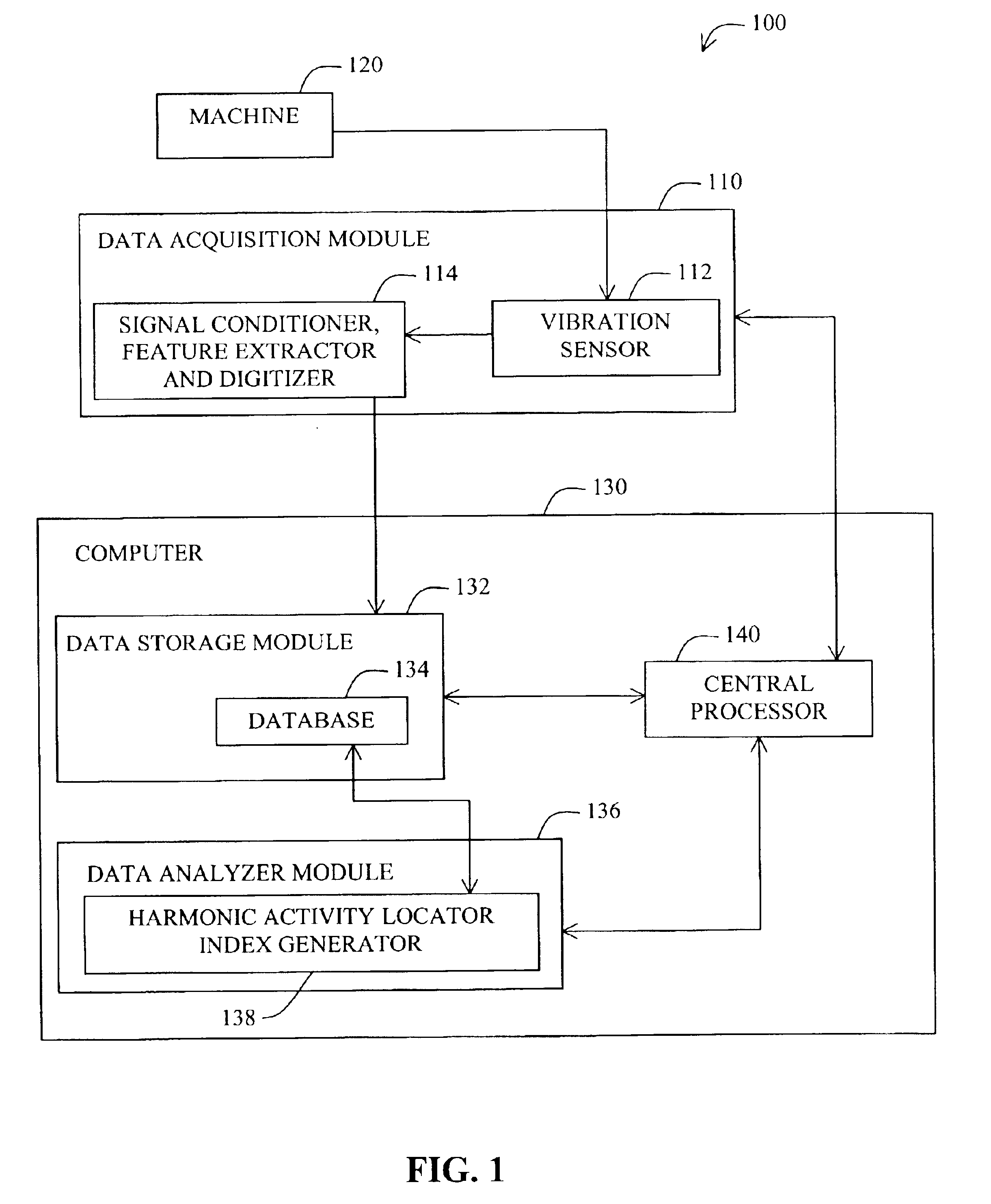
FIG. 1 illustrates a system 100 for detection of a machine component defect in accordance with one embodiment of the invention. The system 100 consists of a data acquisition module 110 in communication with a computer 130. The data acquisition module 110 is coupled to a machine 120 for detecting vibrations of the machine 120. The data acquisition module 110 transmi...


PUM

PropertyMeasurementUnit
frequencyaaaaaaaaaa
defect fundamental frequencyaaaaaaaaaa
harmonic frequenciesaaaaaaaaaa

Abstract

Systems and methods for identifying the presence of a defect in vibrating machinery. An exemplary method comprises analysis of frequency spectrum vibration data of the machine. The method comprises deriving a harmonic activity index based on estimates of the energy associated with the frequency spectrum and the energy associated with the defect's harmonic series. The method may comprise deriving a value K by estimating a value M indicative of the energy of the defect's harmonic series and dividing M by the number of spectral lines corresponding to the defect's harmonic series. The method may further comprise deriving a value R by estimating a value Q indicative of the energy in the frequency spectrum data and dividing Q by the number of spectral lines of the frequency spectrum data. The method further comprises deriving the harmonic activity index based on the estimated K and R. Related systems for executing the methods are also disclosed.

Description

1. Field of the InventionThe invention generally relates to vibration analysis for monitoring the condition of machinery. More specifically, the invention is directed to systems and methods for detecting the development or presence of defects, or other impactive forces, in the components of a machine by analysis of the frequency spectrum of the vibrations of the machine.2. Description of the Related ArtIt is common for industrial and commercial facilities to operate a large number of machines concurrently, many of which may cooperate in a large interdependent process or system. Despite increasingly efficient maintenance programs, at any time some percentage of the machines develop defects that are likely to lead to machine failure. For example, machines having moving parts (e.g., bearings) experience constant friction that results in wear. It is known that bearing failures are a major cause of motor faults. Bearing damage due to wear may not be apparent, however, absent gross damage...

Claims


Application Information

Patent Timeline
Patent Type & Authority Patents(United States)
IPC IPC(8): G01M7/00G01M7/02G01M13/02G01H1/00G01N29/12G01N29/14G01N29/46
CPCG01H1/003G01M7/02G01M13/028G01N29/12G01N29/14G01N29/46
Inventor SMULDERS, ADRIANUS J.WEI, JIM J.BOERHOUT, JOHANNES I.
Owner SKF USA INC
Why Eureka
Try Eureka