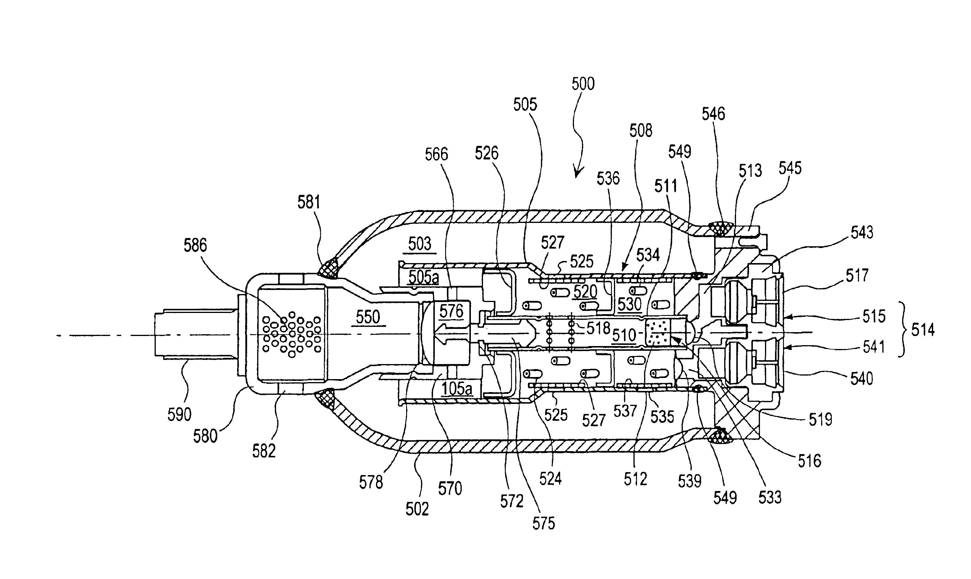
Multi-stage expansion tire hybrid inflator
a hybrid inflator and multi-stage technology, applied in the direction of cycle, vehicular safety arrangement, pedestrian/occupant safety arrangement, etc., can solve the problem of difficulty in some cases in burning the gas generating agent of the above-described composition under normal pressur
- Summary
- Abstract
- Description
- Claims
- Application Information
AI Technical Summary
Benefits of technology
Problems solved by technology
Method used
Image
Examples
embodiments 1 and 2
(1) Embodiments 1 and 2
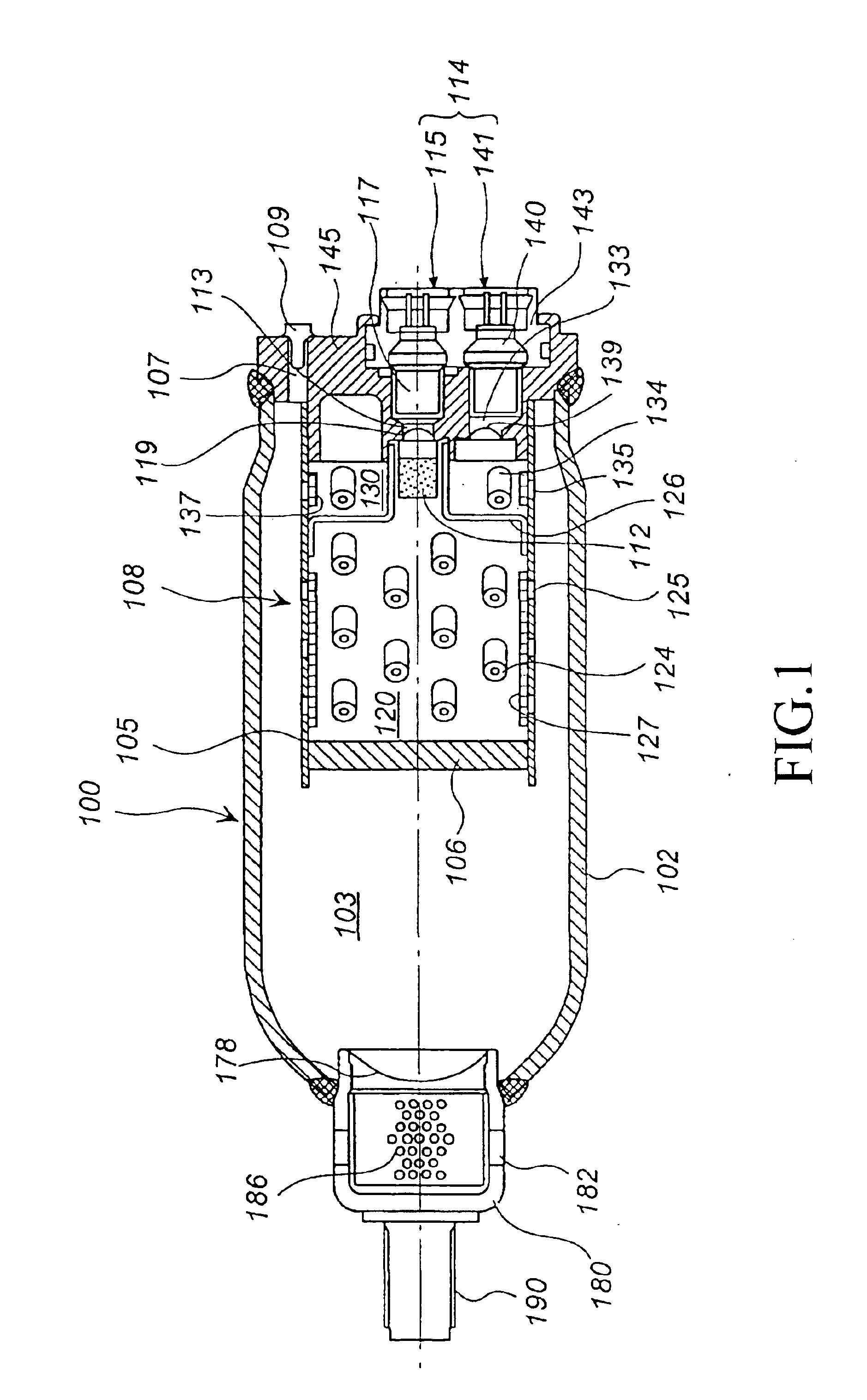
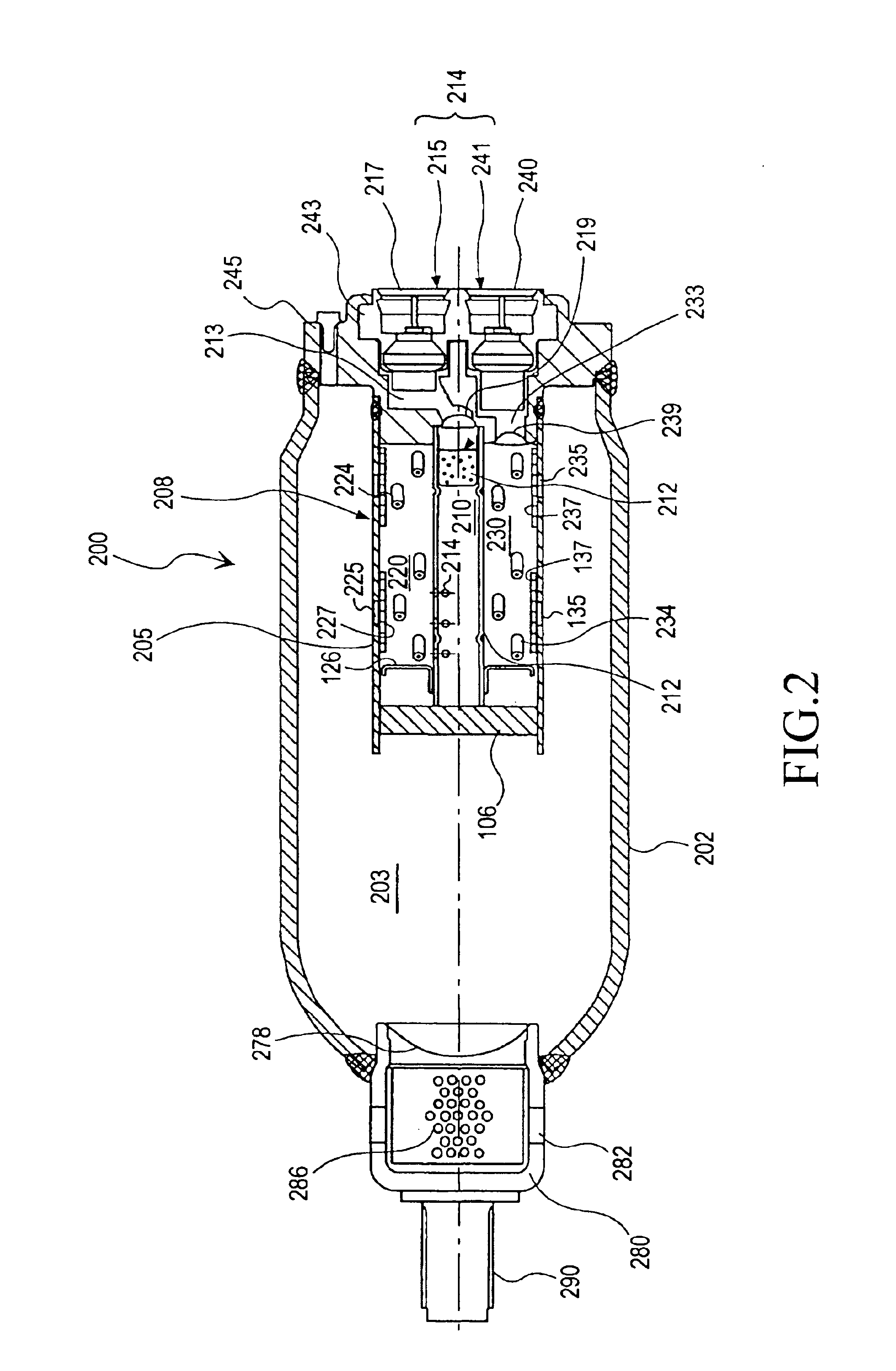
The present invention will be explained in detail with reference to the drawings showing embodiments. FIG. 1 is a sectional view of a hybrid inflator 100 in its longitudinal direction. FIG. 2 is a sectional view of a hybrid inflator 200 of another embodiment in its longitudinal direction.
First, a hybrid inflator shown in FIG. 1 will be explained. As shown in FIG. 1, an inflator housing 102 comprises a cylindrical pressure resisting container, and an inner space 103 is filled with a pressurized medium and maintained at a high pressure.
The pressurized medium is usually charged from a small hole 107 formed in a boss 145 joined to one end portion of the inflator housing 102, and the small hole is closed with a sealing pin 109 after the inflator housing has been filled with the pressurized medium.
A gas generator 108 comprises a first gas generating chamber 120 and a second gas generating chamber 130. The first gas generating chamber 120 comprises a cylindrical gas ...
embodiments 3 and 4
(2) Embodiments 3 and 4
The present invention will be explained in detail with reference to the drawings showing other embodiments. FIG. 3 is a sectional view of a hybrid inflator 300 in the longitudinal direction thereof. FIG. 4 is a sectional view of a hybrid inflator 400 of another embodiment in the longitudinal direction thereof.
The hybrid inflator 300 will be explained based on FIG. 3. As shown in FIG. 3, an inflator housing 302 comprises a cylindrical pressure resisting container, and the inner space 303 thereof is filled with a pressurized medium and maintained at a high pressure. The pressurized medium is usually charged from a small hole 307 formed in a boss 345 connected to one end of the inflator housing 302, and the small hole 307 is closed with a seal pin 309 after the pressurized medium has been charged. The inflator housing 302 can be formed to have a shape such that the outer shape thereof except for a portion in the vicinity of the end portion on the diffuser 380 sid...
embodiments 8 to 12
(4) Embodiments 8 to 12
First, an embodiment of the retainer for a gas generator based on FIG. 8 will be described. FIG. 8 is a schematic sectional view of a retainer for a gas generator and a gas generator in the longitudinal direction.
A retainer 810 for a gas generator 808 comprises a cylinder, having one end closed to form a closed end 812 and the other end open.
All side walls of the retainer 810 for a gas generator 808 may have a constant length or different length in part. For example, in FIG. 8, one side wall 814 may be longer or shorter than the other opposite side wall 816. The side walls are continuously formed together, and there is no clear boundary between the side walls 814 and 816 shown in FIG. 8. However, since the side walls are disposed in a gas generating chambers of the gas generator, it is preferable to divide the side walls into two, i.e., into the side wall 814 and the side wall 816.
In the gas generator 808, the retainer 810 for a gas generator 808 is disposed i...
PUM
 Abstract
Description
Claims
Application Information
 - R&D
- Intellectual Property
- Life Sciences
- Materials
- Tech Scout
- Unparalleled Data Quality
- Higher Quality Content
- 60% Fewer Hallucinations
Browse by: Latest US Patents, China's latest patents, Technical Efficacy Thesaurus, Application Domain, Technology Topic, Popular Technical Reports.
© 2025 PatSnap. All rights reserved.Legal|Privacy policy|Modern Slavery Act Transparency Statement|Sitemap|About US| Contact US: help@patsnap.com


