Rear derailleur device for a bicycle

a rear derailleur and bicycle technology, applied in mechanical devices, transportation and packaging, gearing, etc., can solve the problems of rear derailleur being particularly exposed to shocks and getting caugh

Inactive Publication Date: 2004-09-21
SHIMANO INC
View PDF18 Cites 59 Cited by
  • Summary
  • Abstract
  • Description
  • Claims
  • Application Information

AI Technical Summary

Problems solved by technology

This arrangement is particularly interesting for the user with regards to riding, however, the particular advantage set forth in the present application, does not represent a direct interest to the user, rather it is the limitation of the chain length.
Moreover, the market requires an improved ground clearance, in particular in the case of off-road bicycles, and it becomes clear that the rear derailleur is particularly exposed to shocks and to getting caught, in particular when a great chain length has to be taken up.

Method used


Image

  • Rear derailleur device for a bicycle
  • Rear derailleur device for a bicycle
  • Rear derailleur device for a bicycle

Examples


Embodiment Construction

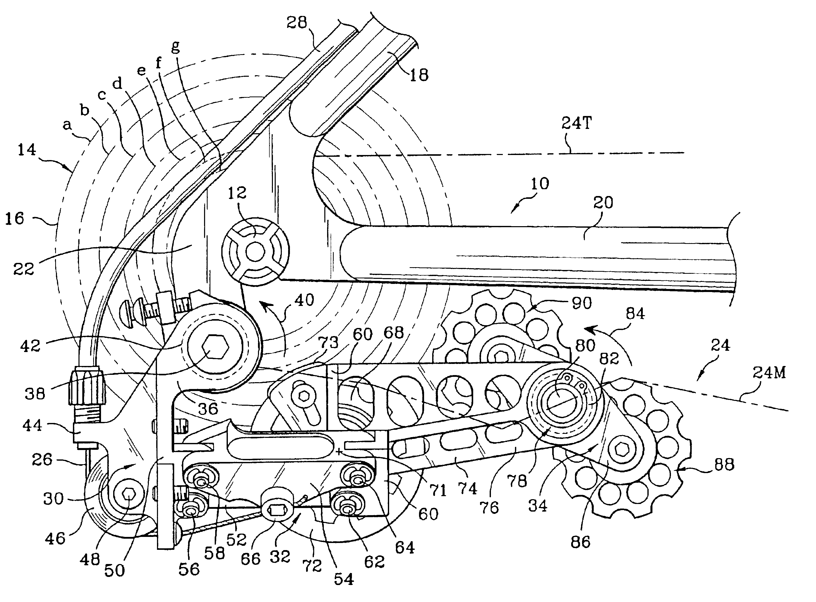
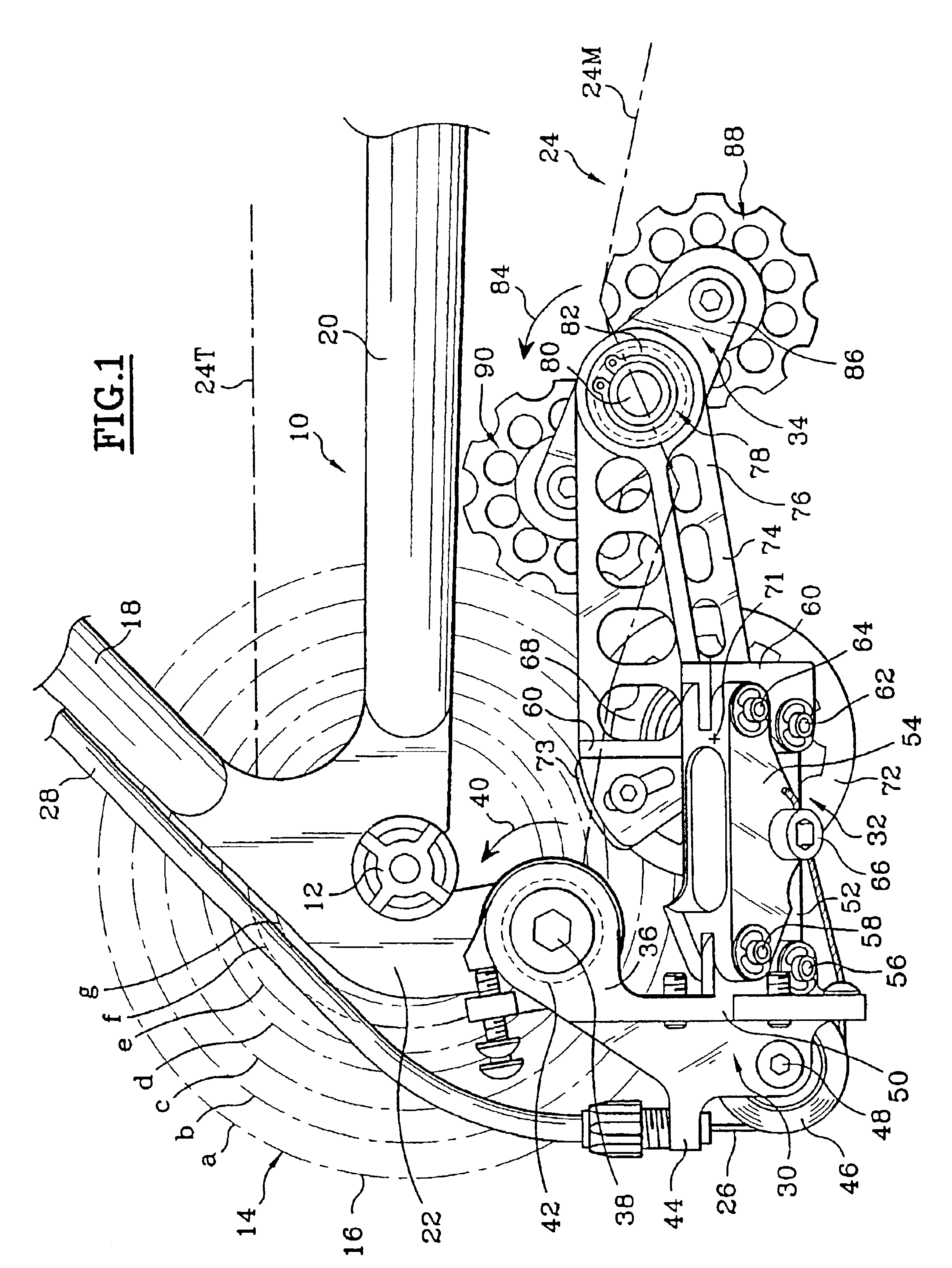
In FIG. 1, the frame 10 of a bicycle is partially represented with the hub axle 12 equipped with a set 14 of pinions 16, in the present case seven pinions a to q, from the largest to the smallest.

The frame 10 comprises in a known and not limiting manner, two tubes 18 and 20 welded together, these two tubes forming a reception plate 22 of the rear derailleur according to the invention.

A chain 24 connects the set 14 of rear pinions with the front disks, the chain being symbolized by a dashed line so as to maintain the Figure's necessary clarity.

A control cable of the rear derailleur has the reference numeral 26 and its sheath 28. The cable issues from a derailleur control which is not represented since this control is not directly relevant for the present invention.

The derailleur according to the Invention comprises three essential parts, a base 30 supporting the derailleur, a deformable guiding / derailleur parallelogram 32, and a movable tension plate, so as to separate the guiding / de...


PUM


Abstract

A rear dérailleur device is provided, in particular for a bicycle equipped with a front dérailleur and a chain connecting a set of pinions with a set of disks. The rear dérailleur device includes a rotatable base provided with a return spring forcing the base in the anti-clockwise direction, guiding/dérailleur means fixedly connected with the base, and a movable tension plate fixedly connected with the guiding/dérailleur means.

Description

1. Field of InventionThe present invention relates to an optimised rear derailleur device for a bicycle, in particular, however, not exclusively appropriate for bicycles also comprising a front derailleur and a gearshift system, the unit being controlled by a synchronized control handle.2. Description of Related ArtAn arrangement of two derailleurs, front and rear, controlled by a single handle is known from the European Patent Application No. 95450012.0.This arrangement is particularly interesting for the user with regards to riding, however, the particular advantage set forth in the present application, does not represent a direct interest to the user, rather it is the limitation of the chain length.The fact namely that the number of combinations of the disks and pinions is reduced into a subunit determined by the entirety of combinations corresponding to the product of the number of pinions by the number of disks, is due to the fact that the alignment of the chain is optimised an...

Claims


Application Information

Patent Timeline
Patent Type & Authority Patents(United States)
IPC IPC(8): B62M9/00B62M9/16B62M9/12B62M9/1246B62M9/1248B62M9/126
CPCB62M9/1248B62M9/126B62M9/16
Inventor SAVARD, FRANCK
Owner SHIMANO INC
Why Eureka
Try Eureka