Cooling system for a metallurgical furnace

a technology of metallurgical furnace and cooling system, which is applied in the direction of furnaces, steam generation plants, lighting and heating apparatus, etc., can solve the problems of positive repercussions on the quality of the water in the tank, and achieve the effect of less expensiv

Inactive Publication Date: 2004-09-21
PAUL WURTH SA
View PDF10 Cites 5 Cited by
  • Summary
  • Abstract
  • Description
  • Claims
  • Application Information

AI Technical Summary

Benefits of technology

It is an object of the present invention to provide a cooling system for a that is less expensive but nevertheless more reliable than existing cooling systems on metallurgical furnaces.
In accordance with another important aspect of the present invention, the pressure vessel means is not only used as pressurised emergency water reserve, but also as pressurised make-up water reserve, which advantageously replaces a make-up water reserve and a make-up water pump. In this case, the system further comprises a make-up water injection line with a make-up water injection valve connected between the closed cooling circuit and the pressure vessel so as to be capable of injecting pressurised emergency water from the pressure vessel as make-up water into the closed cooling circuit. This solution does not only provide important cost advantages, it also warrants that the emergency water reserve is regularly renewed, which has of course a positive repercussion on the quality of the water in the tank.
In order to reduce the time between two successive discharges and to make thereby the emergency cooling even more reliable, the pressure vessel means advantageously comprises a first and a second pressure vessel that are connected in parallel to the emergency feed line. This cooling system then further includes: a first gas line connected through a first gas valve to the first pressure vessel, for supplying a pressurised gas into the first pressure vessel; a second gas line connected through a second gas valve to the second pressure vessel, for supplying a pressurised gas into the second pressure vessel; a first vent line with a first vent valve for venting the first pressure vessel; a second vent line with a second vent valve for venting the second pressure vessel; an emergency water return line collecting the cooling water flowing through the open emergency overflow valve; a first emergency water return valve connecting the emergency water return line to the first pressure vessel; a second emergency water return valve connecting the emergency water return line to the second pressure vessel; and a pressure equalising line with a pressure equalising valve connected between the first and the second pressure vessel. This system allows to recuperate at least part of the pressurising gas after for a subsequent emergency discharge and to reduce thereby the time required for re-pressurising the pressure vessel means after a discharge. It enables to bridge the time laps until the end of the power failure or until the start of an emergency pump or an emergency power unit by successive emergency water discharges of the first and the second pressure vessel. It follows that the two pressure vessels can be designed for containing a rather small volume of emergency water, without affecting the reliability and effectiveness of the emergency cooling function.
It will also be appreciated that the present invention provides a blast furnace cooling circuit design which makes it possible to considerably reduce the piping costs. Such a blast furnace cooling circuit comprises at least a first sub-circuit connected to at least a second sub-circuit by means of at least one booster pump.
Another important aspect is a closed expansion vessel connected to the closed cooling circuit, wherein the closed expansion vessel is pressurised with a gas. This solution enables a better pressure control and has a positive aspect on water quality.

Problems solved by technology

This solution does not only provide important cost advantages, it also warrants that the emergency water reserve is regularly renewed, which has of course a positive repercussion on the quality of the water in the tank.

Method used


Image

  • Cooling system for a metallurgical furnace
  • Cooling system for a metallurgical furnace
  • Cooling system for a metallurgical furnace

Examples


second embodiment

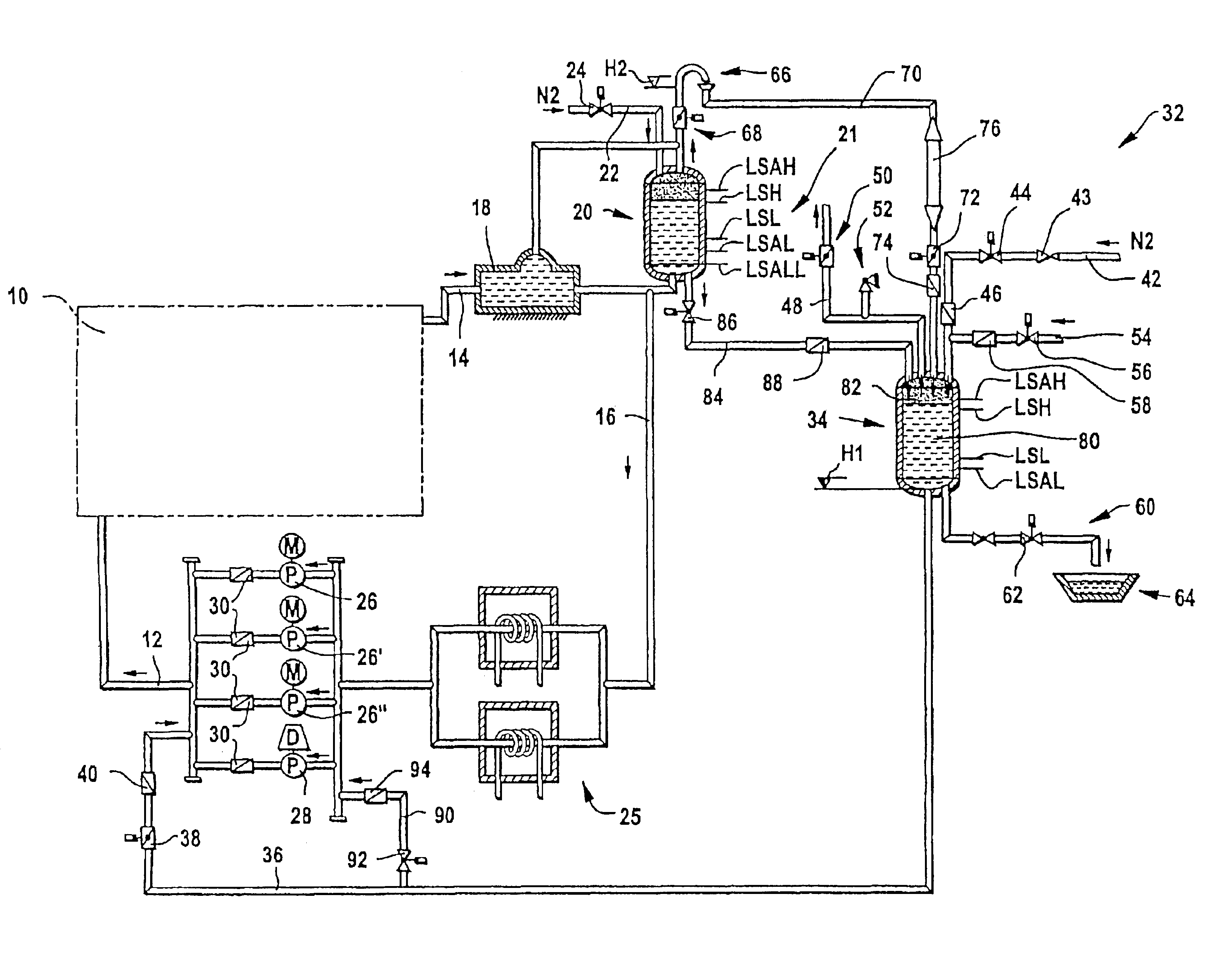
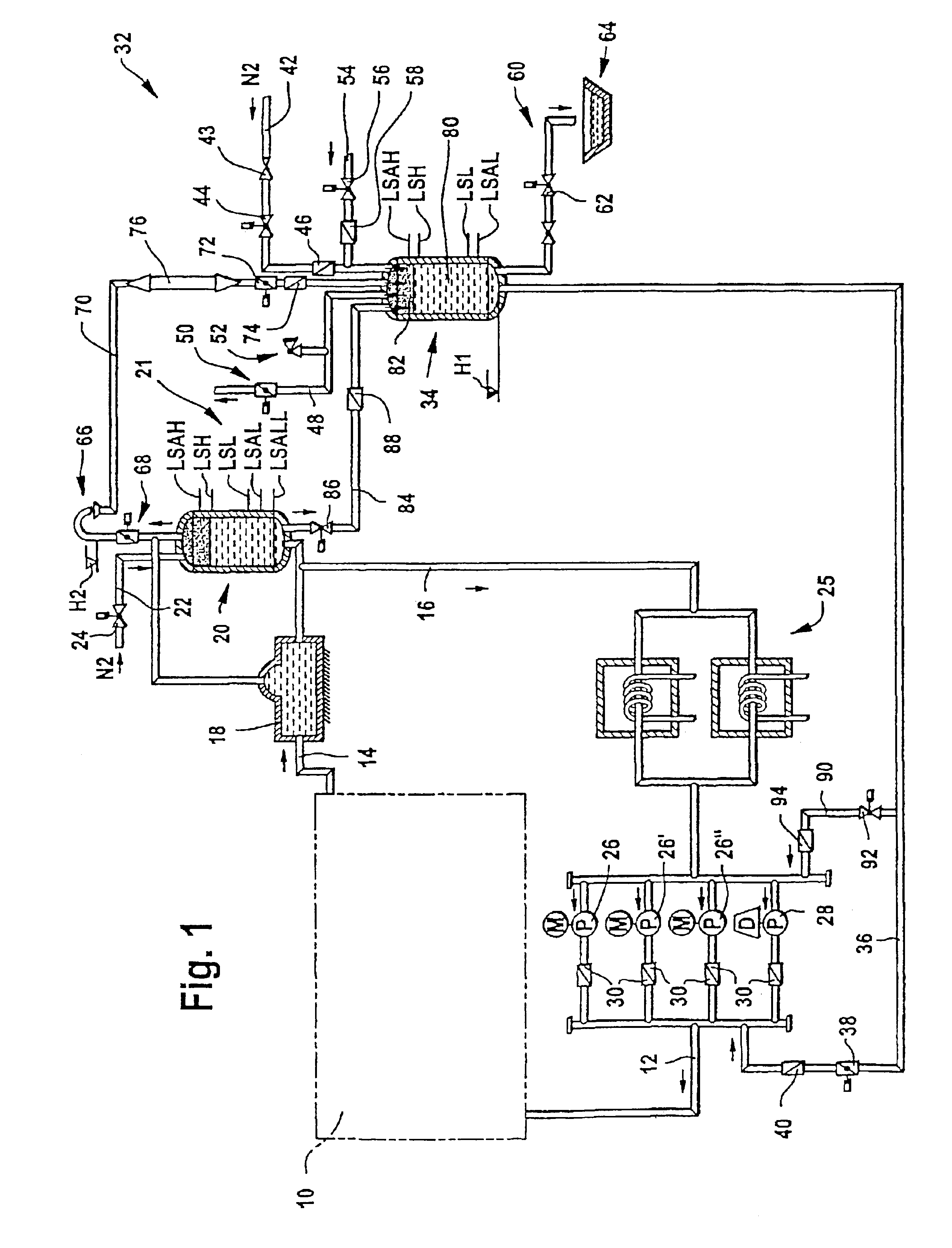
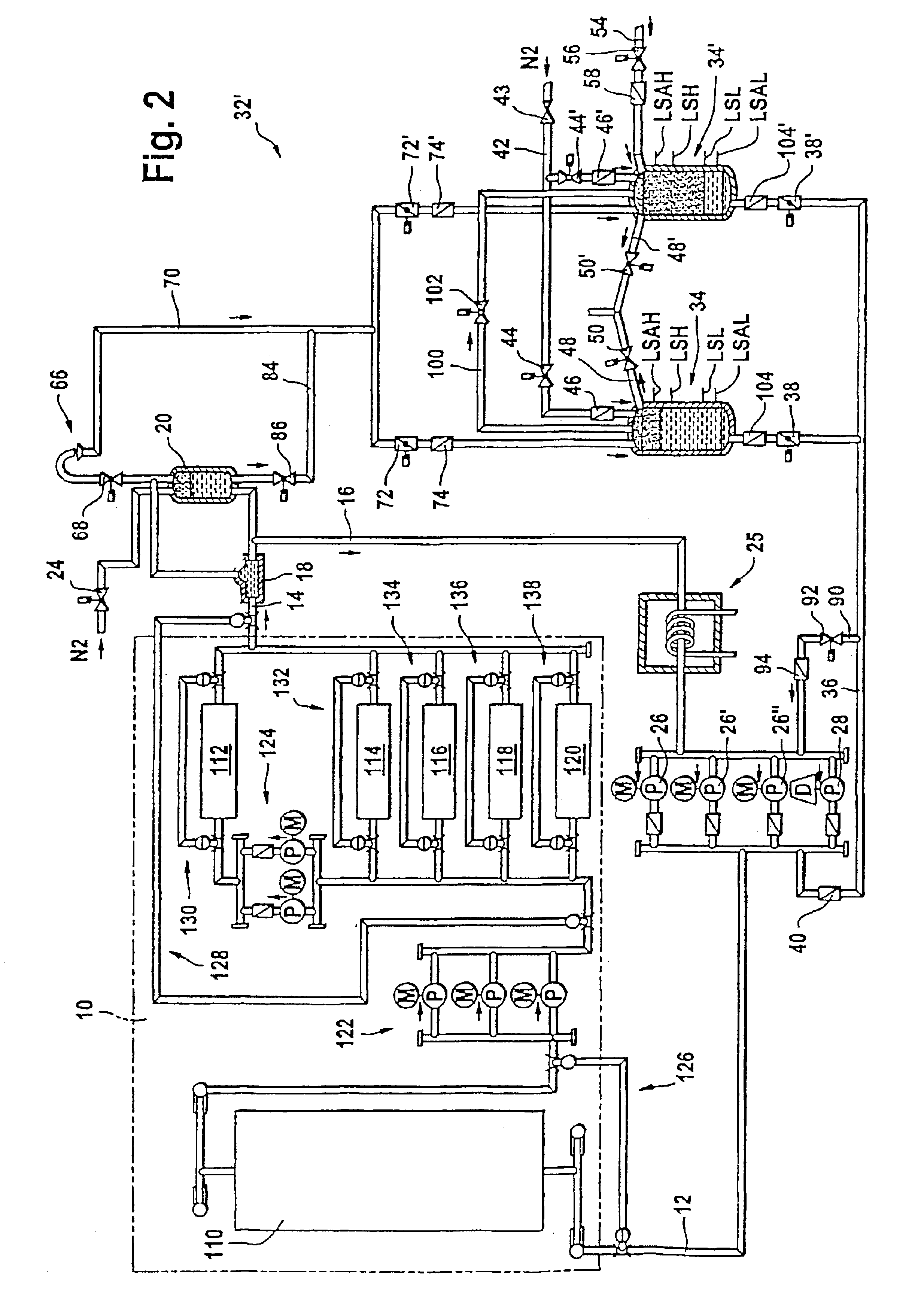
a cooling system for a blast furnace in accordance with the invention will now be described with reference to FIG. 2.

The cooling system of FIG. 2 differs from the cooling system of FIG. 1 mainly in that the emergency cooling system 32' comprises a second pressure vessel 34' connected in parallel with the pressure vessel 34, which is called hereinafter the first pressure vessel 34. Both pressure vessels 34, 34' are this time located at ground level. A gas line 42 is connected through a first gas valve 44 and a first non-return valve 46 to the first pressure vessel 34 and through a second gas valve 44' and a second non-return valve 46' to the second pressure vessel 34'. A first vent line 48 with a first vent valve 50 equips the first pressure vessel 34 and a second vent line 48' with a second vent valve 50' equips the second pressure vessel 34'. An emergency water return line 70 collects the cooling water flowing through the open emergency overflow valve 68. A first emergency water re...


PUM

PropertyMeasurementUnit
diameteraaaaaaaaaa
atmospheric pressureaaaaaaaaaa
volumeaaaaaaaaaa

Abstract

A cooling system for a blast furnace includes a cooling circuit (10) closed by a return line (16) and at least one circulation pump (26, 26', 26'') for circulating cooling water through the closed cooling circuit. An emergency feed line (36) with an emergency feed valve (38), which opens in case of a power failure, is connected to the cooling circuit (10). An emergency overflow valve (68) is located at the highest point of the closed cooling circuit (10). This emergency overflow valve (68) opens in case of a power failure, so that the closed cooling circuit (10) becomes an open cooling circuit (10) with an atmospheric pressure discharge at its highest point. A pressure vessel (34), which is connected to the emergency feed line (36), contains a certain volume of emergency water which is pressurised by a gas, so that, in case of a power failure, an emergency water flow establishes through the open cooling circuit (10).

Description

The present invention relates to a cooling system for a metallurgical furnace, in particular a blast furnace.Known blast furnace cooling systems are cooling water circuits, in which cooling water is circulated in a closed circuit by electric circulation pumps. The elements of the blast furnace to be cooled (i.e. the cooling staves and cooling boxes of the furnace walls, the tuyeres and hot blast equipment) are regrouped in several parallel branches or sub-circuits, which are hydraulically balanced so that a predetermined flow of cooling water circulates through each sub-circuit. A common return line, comprising one or more heat exchangers, closes the cooling circuit.In case of an electric power failure the cooling is interrupted because the electric circulation pumps do not work. To protect cooled elements against damages in such a case, it is known to provide an emergency cooling system. Such an emergency cooling circuit comprises a gravity tank that is mounted on a support structu...

Claims


Application Information

Patent Timeline
Patent Type & Authority Patents(United States)
IPC IPC(8): C21B7/10C21B7/00
CPCC21B7/103
Inventor LY, GIANG KIENSCHMELER, ROBERT
Owner PAUL WURTH SA
Why Eureka
Try Eureka