Modular system for securing flat panels to a curved support structure

a technology of rigid panels and modules, applied in the direction of photovoltaic supports, heat collector mounting/supports, lighting and heating apparatus, etc., can solve the problems of brittle materials, inability to easily bend, and high manufacturing costs of components

Inactive Publication Date: 2004-10-05
KAWNEER COMML WINDOWS LLC
View PDF20 Cites 39 Cited by
  • Summary
  • Abstract
  • Description
  • Claims
  • Application Information

AI Technical Summary

Problems solved by technology

However, such elements are both expensive and time consuming to manufacture.
Also, these types of roofs have presented a persistent problem for using glass or glass-like transparent materials.
Typically, such materials are brittle and cannot be easily bent to fit the contour of a curved roof.
Although such materials can sometimes be made in a curved or convex shape, such shapes are relatively difficult and expensive to manufacture.
Therefore, such gaskets and similar elements were limited in that they had to match the contour or curvature of a particular rafter or other support member.
Another difficulty with such gaskets and similar elements was that they often required the use of multiple lengths or types of screws or other fasteners.
This resulted in a large inventory of parts for assembly and made the assembly more complicated and time consuming.
However, in some cases these designs required large modules, curved metal profiles, or multiple shell extrusions; all of which were difficult and expensive to design, construct and install.
In some cases, the modules incorporated relatively large, arc-shaped elements that were difficult and expensive to construct and transport to the place of assembly.
In other cases, modular systems such as a split mullion design were found to be inefficient in that they incorporated redundant junctions for the modular units.
This resulted in additional parts that increased the weight and cost of the roof.
In some instances, these systems incorporated exposed exterior caps, gaskets and fasteners that presented potential leak points and also complicated the maintenance and cleaning of the roof after construction.
In those situations, the exterior caps of the prior art modular systems shaded the photovoltaic cells and tended to trap dirt so as to increase the difficulty and expense of cleaning the cells.
Another objection to some prior art systems has been that their design requires numerous parts, large fasteners or has otherwise resulted in an assembly with a cluttered appearance or that is otherwise aesthetically objectionable.
Also, prior art systems, including modular type systems, have been mechanically complicated.
Still another objection to systems for securing flat panels to a curved support structure as known in the prior art has been that the known designs were deficient in some practical respects.
For example, some designs did not provide for certain practical features such as a maintenance walkway.

Method used


Image

  • Modular system for securing flat panels to a curved support structure
  • Modular system for securing flat panels to a curved support structure
  • Modular system for securing flat panels to a curved support structure

Examples


Embodiment Construction

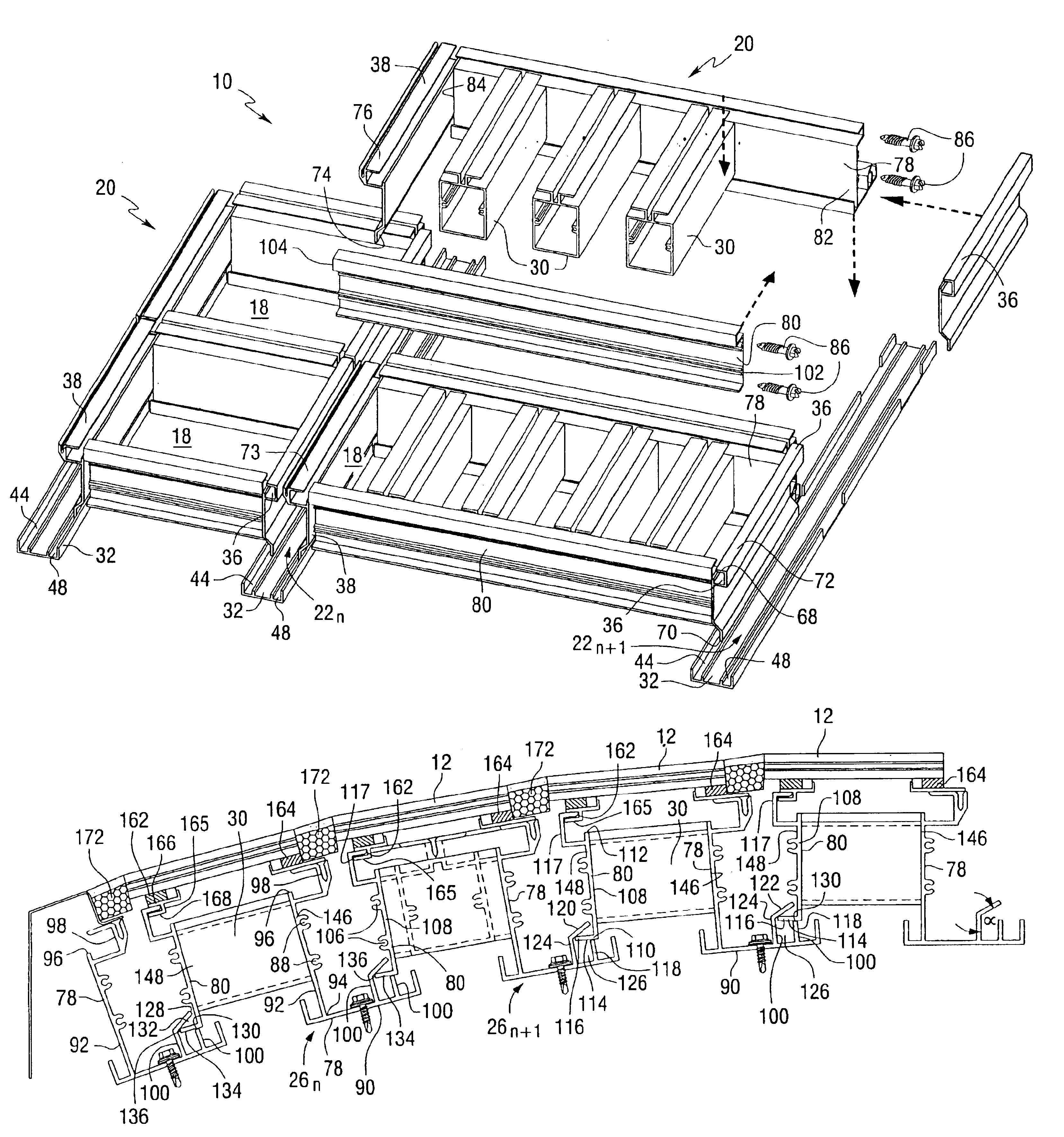
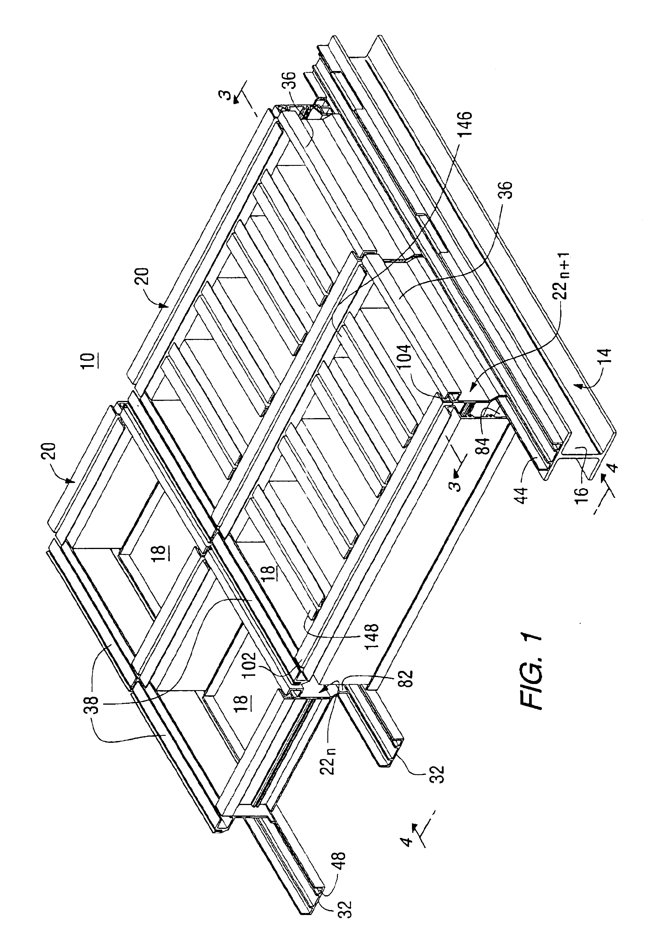
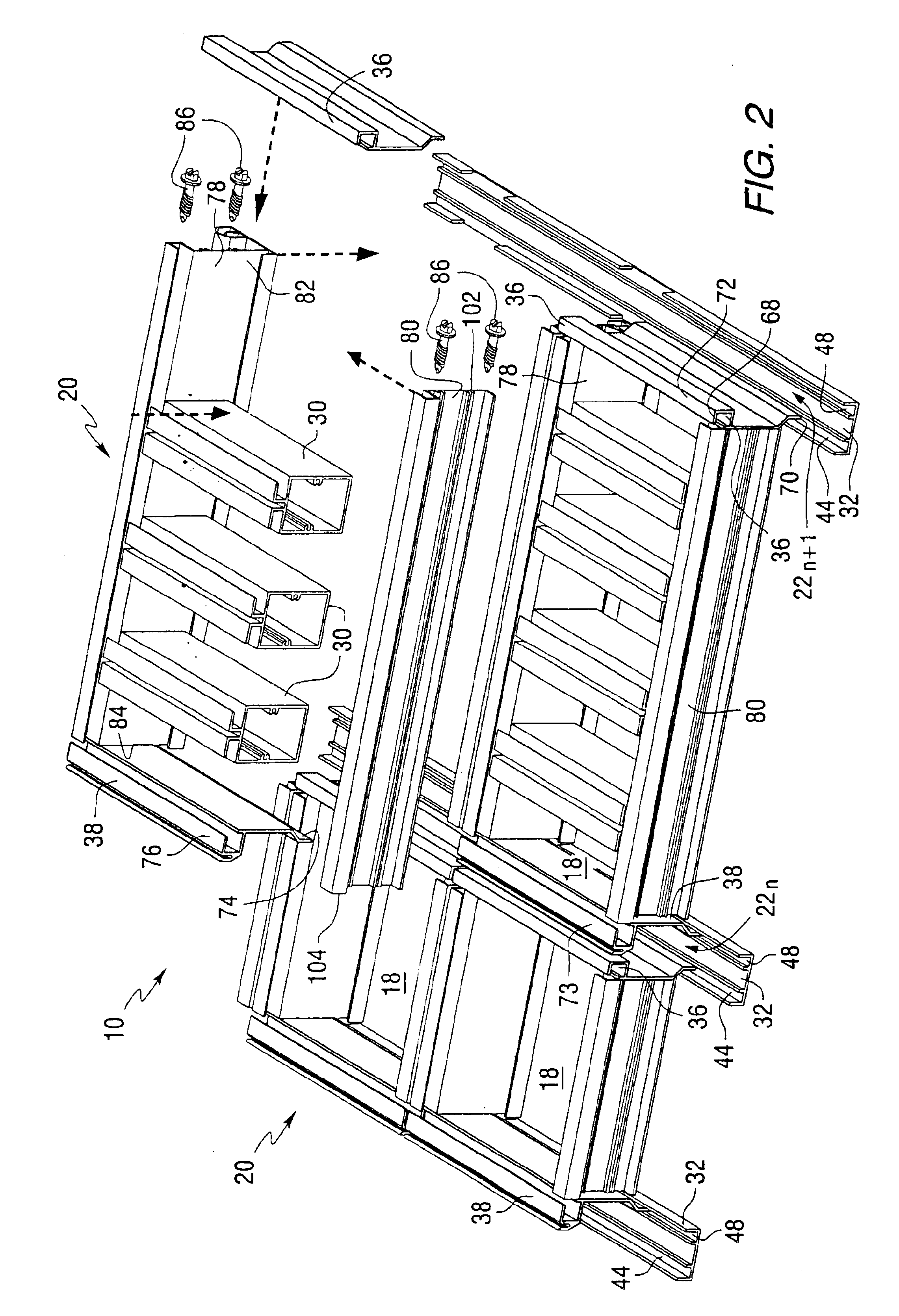
A presently preferred embodiment of the presently disclosed invention is shown and described in connection with FIGS. 1-4 which show a modular system 10 for attaching planar panels such as photovoltaic panels 12, to a curved support structure 14. In particular, the example of FIGS. 1-4 relates to attaching flat panels, such as photovoltaic panels 12, to a domed or vaulted roof support structure 14. Typically, domed or vaulted roofs or canopies have a support structure that includes a multiple of rafters 16 that support a cover. The cover is formed from a multiple of panels 12 that are individually secured to the roof support structure by the modular system 10. The rafters 16 are curved according to the design of the particular roof to accomplish the intended structural and aesthetic purposes. The modular system 10 accommodates the curvature of the rafters and also secures the panels 12 to the rafters 16 as herein is more particularly described.

Each of the panels 12 is secured in a r...


PUM


Abstract

A modular system (10) for attaching planar panels (12) to a curved support structure (14). The system includes modules (20) that are defined between a transverse hook support panel (36) and a transverse plate support panel (38) and between a base member (78) and a pivot member (80). Each module (20) defines one or more cells (18) in accordance with the use of transverse cross-support members (30). Each panel (12) is secured on a respective cell (18).

Description

1. Field of the InventionThe subject invention relates to systems for affixing transparent panes to a curved canopy and, more particularly, systems for securing flat rigid panels to a curved canopy.2. Description of the Prior ArtVarious types of canopies and other roof structures have been developed and used for many years. Some of these structures incorporate the use of a transparent or translucent cover that shields precipitation, but that allows natural sunlight to pass through. Examples of such structures are shown and described in U.S. Pat. Nos. 6,088,978, 5,291,705, 4,862,657, 4,987,705, 5,103,603, 4,621,472, 5,797,225, 5,617,682, 5,509,250, 5,394,664, 5,163,257, and 5,580,620.Prior roof structures have been dome-shaped or otherwise curved or vaulted for aesthetic and various other reasons. Typically, these roofs have been "stick built" meaning that they are assembled on-sight from specially designed elements. These designs generally involve vertical structural shapes that, in...

Claims


Application Information

Patent Timeline
Patent Type & Authority Patents(United States)
IPC IPC(8): E04D13/03E04D3/08E04D3/02E04D13/18H01L31/042
CPCE04D3/08E04D13/032F24J2/5205H02S20/00F24J2/5211E04D2003/0818Y02B10/12Y02E10/47Y02E10/50F24S25/20F24S25/33Y02B10/10
Inventor PLEVYAK, MICHAEL
Owner KAWNEER COMML WINDOWS LLC
Why Eureka
Try Eureka