
Method and apparatus for recognising a radar target

a radar target and target technology, applied in the field of radar target recognition methods and apparatuses, can solve the problems of not being able to provide up-to-date information on a rapidly changing scene, unsuitable for use with mti radars, and not being able to classify all types of scenes

Inactive Publication Date: 2004-10-05
QINETIQ LTD
View PDF6 Cites 31 Cited by
  • Summary
  • Abstract
  • Description
  • Claims
  • Application Information

AI Technical Summary

Benefits of technology

The invention provides the advantage that moving targets may be classified without recourse to a large database of radar signature data.

Problems solved by technology

However, if a scene under observation contains many different types of targets, a human operator, however trained, cannot classify all types in the scene and cannot provide up-to-date information on a rapidly changing scene.
They are unfortunately unsuitable for use with MTI radars which are mainly low resolution sensors: MTI radars show target images as single bright point objects with no spatial structure in either range or azimuth.
If the radar operates at higher bandwidth then the radar signature will have a higher slant range resolution and the target will be resolved in range, e.g. a bandwidth of 500 MHz will give a slant range resolution of 0.3 m. However, it is not possible to get higher azimuth resolution.
Thus at best an MTI radar can only obtain 1-dimensional high range resolution profiles of moving targets.
Limited success has been achieved in developing recognition algorithms that exploit the 1-dimensional high range resolution profile of targets for classification.
There are, however, two main drawbacks with a range profile classifier.
Firstly, high bandwidth radars are more expensive and it is more difficult to extract high range resolution profiles because moving targets can migrate through a succession of range cells and causing considerable difficulties.
Secondly, target range profiles are very sensitive to changes in target orientation to the radar and the target physical build characteristics.
This presents a major problem for classifiers using template matching, because they carry out recognition by comparing the range profile of an unknown target with a set of templates and choosing the class that yields the best match: this relies on having a template set that contain every single independent realisation of target signature for a class of targets to be recognised.
A target classifier based on template matching would require a prohibitively large number of stored Doppler profiles.

Method used


Image

  • Method and apparatus for recognising a radar target
  • Method and apparatus for recognising a radar target
  • Method and apparatus for recognising a radar target

Examples


Embodiment Construction

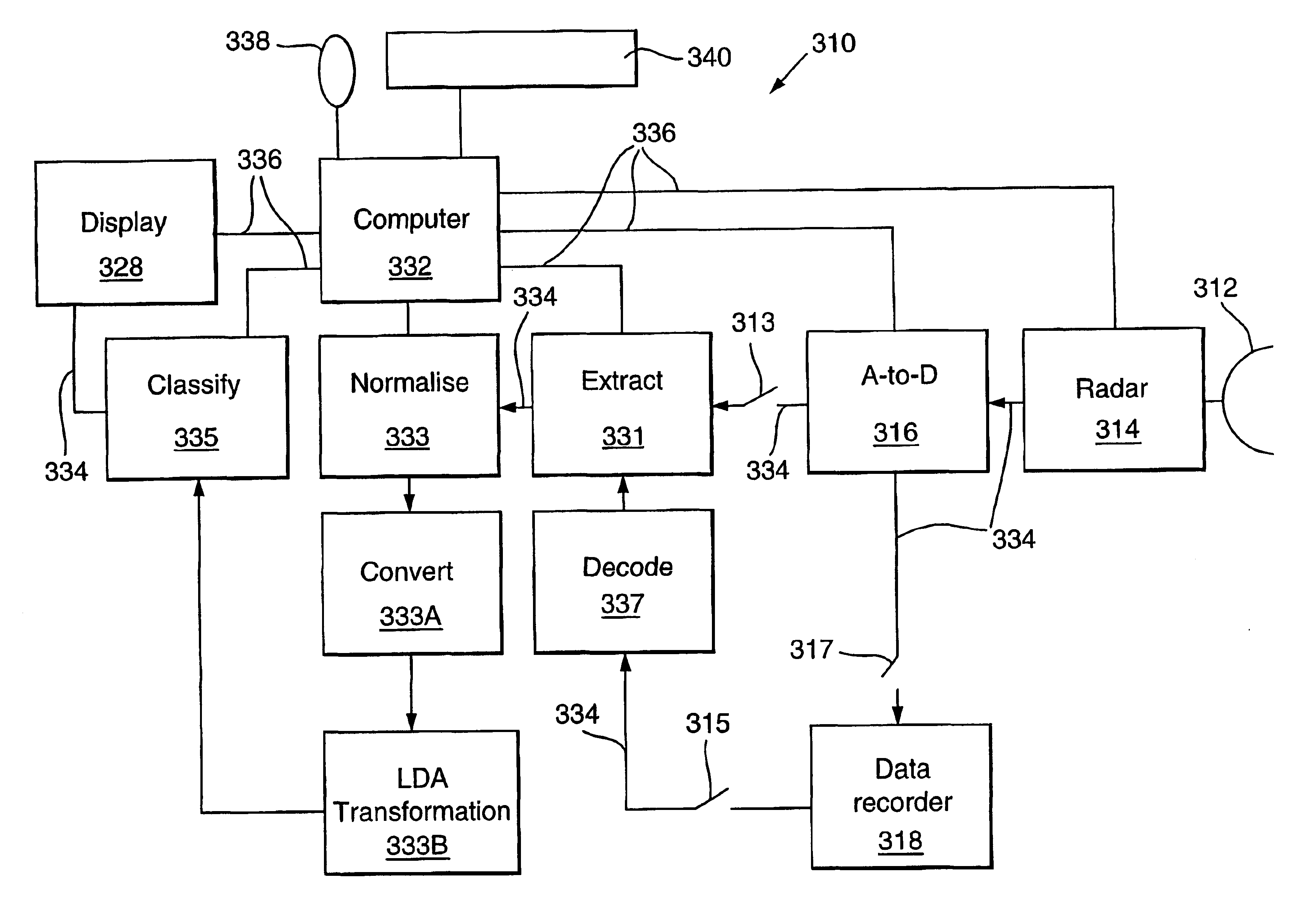
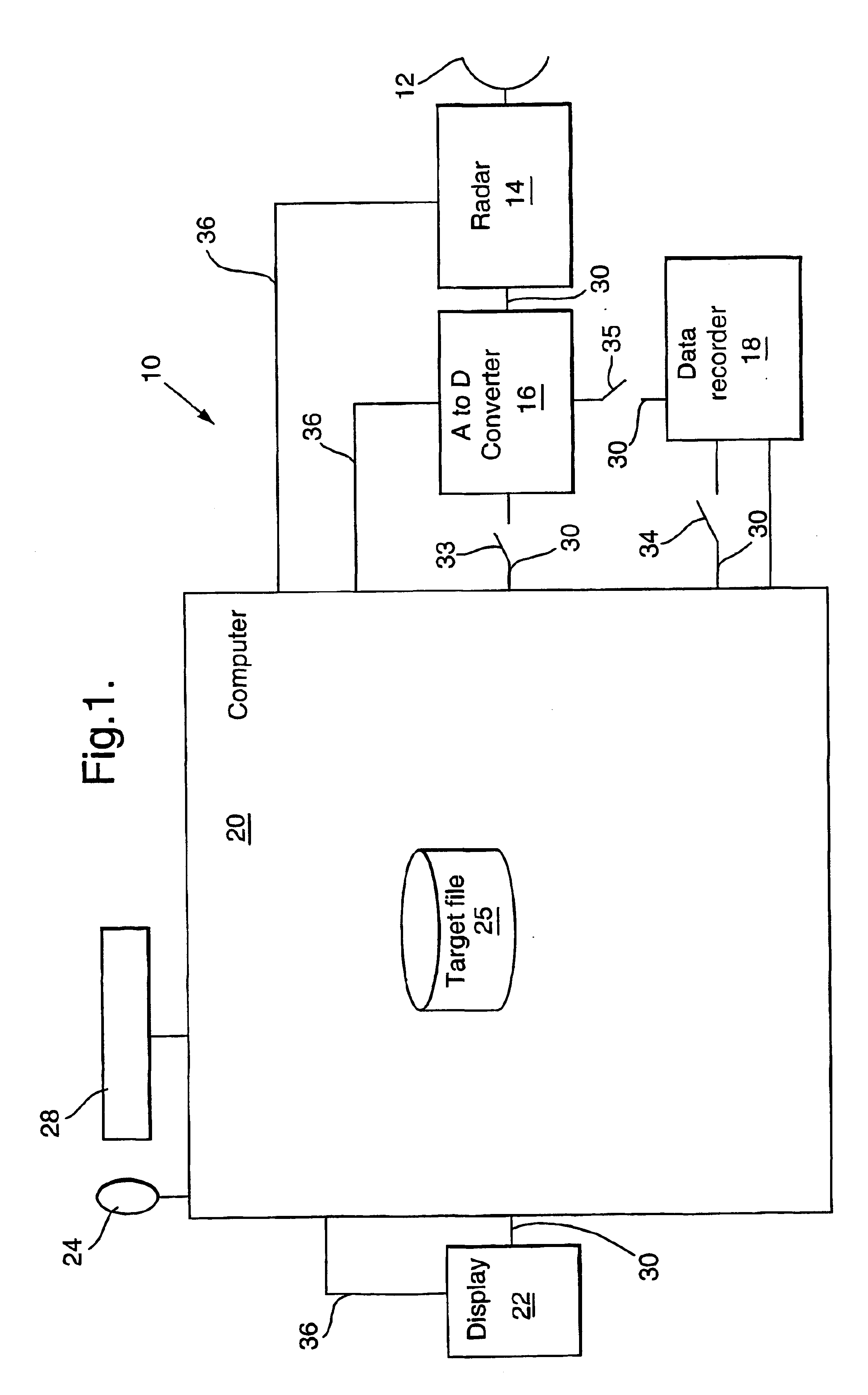
Referring to FIG. 1 there is shown a radar target recognition system of the invention indicated generally by 10. The system 10 comprises an antenna 12, a radar device 14, an analogue-to-digital (A to D) converter 16, a data recorder 18, a computer 20 and a display device 22. The computer 20 is under operator control via a mouse 24 and a keyboard 28. Data passes between parts of the system 10 along data lines 30, of which those between the computer and A-to-D converter 16, the computer 20 and data recorder 18, and the A-to-D converter 16 and data recorder 18 include respective switches 33, 34 and 35. Control lines 36 provide for computer-generated control signals to pass to the radar device 14, the A-to-D converter 16 and the display device 22. A communication line 37 is provided for passing messages between the computer 20 and data recorder 18.

The antenna 12 is a fixed, high gain dish antenna. The radar device 14 is a "Midas" radar which is manufactured by Thales-Wells and described...


PUM


Abstract

A method of recognizing a radar target comprises producing a sequence of Doppler spectra of radar returns form a scene and producing therefrom a sequence of Doppler feature vectors for a target in the scene. Hidden Markov modelling (HMM) is then used to identify the sequence of Doppler feature vectors as indicating a member of a particular class of targets. HMM is used to identify the sequence of Doppler feature vectors by assigning to each feature vector an occurrence probability by selecting a probability distribution or state from a set thereof associated with a class of targets, multiplying the occurrence probabilities together to obtain an overall probability, repeating for other probability distributions in the set to determine a combination of probability distributions giving highest overall probability for that class of target, then repeating for at least one other class of targets and selecting the target class as being that which yields the highest overall occurrence probability.

Description

1. Field of the InventionThis invention relates to a method of and an apparatus for recognising a radar target.2. Discussion of Prior ArtMoving target identification (MTI) radars are known. Such radars can provide all-weather, day and night surveillance capability and have a wide-area search capability as a result of rapid scanning of the radar beam. An MTI radar may be used to provide location information relating to a moving target and may also be used to identify a target as belonging to a particular class of targets. For example an MTI radar may be used to classify a target as being a person, a wheeled vehicle or a tracked vehicle. Presently, the task of target recognition using an MTI radar is carried out by a human operator. In one known MTI radar, echo signals from targets are converted to audio signals which are output to an audio speaker. To identify a particular target, the radar's antenna is directed to a target for several seconds during which time an operator listens to...

Claims


Application Information

Patent Timeline
IPC IPC(8): G01S7/02G01S13/524G01S13/00G01S7/41G06K9/32G06K9/62G01S7/292
CPCG01S7/415G06K9/6297G06K9/3241G01S13/524G01S7/2923G06V10/255G06F18/295
Inventor JAHANGIR, MOHAMMEDPONTING, KEITH M
Owner QINETIQ LTD
Learn More