Removing radar absorbing coatings

a radar and coating technology, applied in the direction of electric/magnetic/electromagnetic heating, nuclear engineering, liquid cleaning, etc., can solve the problems of large amount of carbon dioxide emissions, large volume of waste products, and ineffective mechanical abrasion of rubbery polymer coatings, etc., to minimize or eliminate thermal and mechanical damage to substrates, the effect of reducing the production of volatile compounds

Inactive Publication Date: 2004-10-12
THE UNITED STATES OF AMERICA AS REPRESENTED BY THE SECRETARY OF THE NAVY
View PDF3 Cites 11 Cited by
  • Summary
  • Abstract
  • Description
  • Claims
  • Application Information

AI Technical Summary

Benefits of technology

It is another object of this invention to minimize production of volatile compounds and other hazardous waste and byproducts resulting from removal of coatings from metallic and non-metallic substrates.
Another object of this invention is to minimize or eliminate thermal and mechanical damage to substrates to which coatings are secured.
This invention is directed to a process for quickly removing a coating, particularly a radar absorbing coating, adhering to a substrate by the use of microwave energy, the process intending to minimize or eliminate thermal and mechanical damage to substrates and to minimize production of volatile compounds and other hazardous waste and byproducts.
In a preferred embodiment, a millimeter-wave beam source of microwave energy of high frequency is used to rapidly heat a metal or ceramic-filled radar absorbing polymeric coating bonded to a substrate. If the coating is of high dielectric constant and has high dielectric loss and there is an electrically conducting reflective layer between the coating and the composite layer, the millimeter-wave beam source will deposit significant amounts of energy in the coating with the peak in the energy typically occurring within the thickness of the coating. For sufficient amounts of energy deposition, i.e., sufficient power density in the beam, the interior of the coating is rapidly heated to a temperature of perhaps 200-400.degree. C., which degrades the polymeric constituents of the coating, producing volatiles and gases within the bulk of the coating and causes the coating to debond and separate from the substrate. During this process, very little heat is transferred to the substrate, resulting in minimal heating of the substrate and no thermal damage to the substrate. Following this process, the debonded and degraded coating can be physically removed from the substrate with no damage to the substrate surface.
The relatively low temperature below the coating can also be ascribed to the insulating property of the coating and the high thermal conductivity of the metallic layer (aluminum) disposed between the coating and the fiber reinforced polyester layer. However, the selectivity of the microwave heating is apparent to deposit energy within the coating so that only the coating is thermally degraded by scission, or otherwise, of the polymer bonds within the coating or selective heating of the adhesive securing the coating to the substrate so that removal of the coating from a substrate is facilitated.
This process enjoys the advantage of the capability to minimize production of volatile matter and other hazardous waste and byproducts. When heating a coating material that contains volatile components, evolution of such components cannot effectively be eliminated but evolution thereof can be minimized and made tolerable to the operation. If the coating matrix is polyurethane, it is relatively impermeable to volatile compounds and it is hypothesized that the volatile components generated during heating and decomposition of the coating matrix form as of a sac encased in a polymer. The sac enlarges as the ambient temperature increases and there is a risk that the sac will rupture and release its contents of volatile compounds to the surroundings. Within the coating, many such sacs are formed during heating of the coating materials and some of them may rupture but most of them do not and as the energy is turned off and the system begins to cool, volume of the sacs becomes smaller and volume of the volatile compounds also decreases with the result that by the time the system reaches ambient temperature, it stabilizes and the volatile components remain in the coating. The reason that evolution of volatile components in such coating is minimized is because the heating is selective and is directed at specific portion(s) of the coating. Pursuant to the invention herein, only a portion of the coating is heated and not the entire coating as in prior art. Therefore, heating of only a portion of the coating thickness produces only a portion of volatile components and selection of a relatively non-porous coating matrix reduces evolution and / or production of volatile components and other hazardous waste and byproducts.

Problems solved by technology

Conventional mechanical abrasion using conventional abrasives and wire brushes are rather ineffective in removing some of the coatings which are based on rubbery polymers, such as urethanes used for all-around purposes, neoprenes used for their weather resistance, nitrile rubbers used for their fuel and oil resistance, and fluoro-elastomers used for their excellent operating temperature range.
In addition, this method produces substantial volume of waste products, including mixtures of abrasives and coating residue, requiring special disposal.
Grit blasting, which has been done with conventional abrasives, plastic abrasives and, most recently with crushed dry ice as the abrasive, is not very effective against the rubbery coatings, suffers from problems with waste and with the use of dry ice which results in evolution of substantial amounts of carbon dioxide emissions as well.
Mechanical scraping can be done successfully but it is very labor-intensive, requires skilled workers, and carries with it risks of significant damage to the substrate to which the coating is or was bonded.
Heat lamps are limited in maximum power density deposited in the coatings and heat the coating from the outward surface inward, depending on heat conduction through the low conductivity coating to degrade the bulk of the coating.
As a result, significant time is involved in raising the entire coating thickness to a temperature that would degrade it, and the substrate is consequently heated as well.
Such techniques also result in large emissions of volatile organic compounds as the outer layer of the coating is heated to very high temperature.
However, this is still a surface process and the laser radiation penetrates only a very short distance, of approximately 1 micron, into the coating resulting in a relatively slow material removal process, that has to work its way down through the coating thickness and is limited by the ablation products blocking the incident radiation, rather then removing it completely in one operation.
The increased need for radar absorbing materials has resulted from two ongoing developments: the first being the greater number of electronics systems being incorporated into vehicles, including aircraft and ships, which has resulted in a corresponding growth in electromagnetic interference.
These problems include false images, increased clutter on radars and reduced performance because of system-to-system coupling.

Method used


Image

  • Removing radar absorbing coatings
  • Removing radar absorbing coatings
  • Removing radar absorbing coatings

Examples


example 2

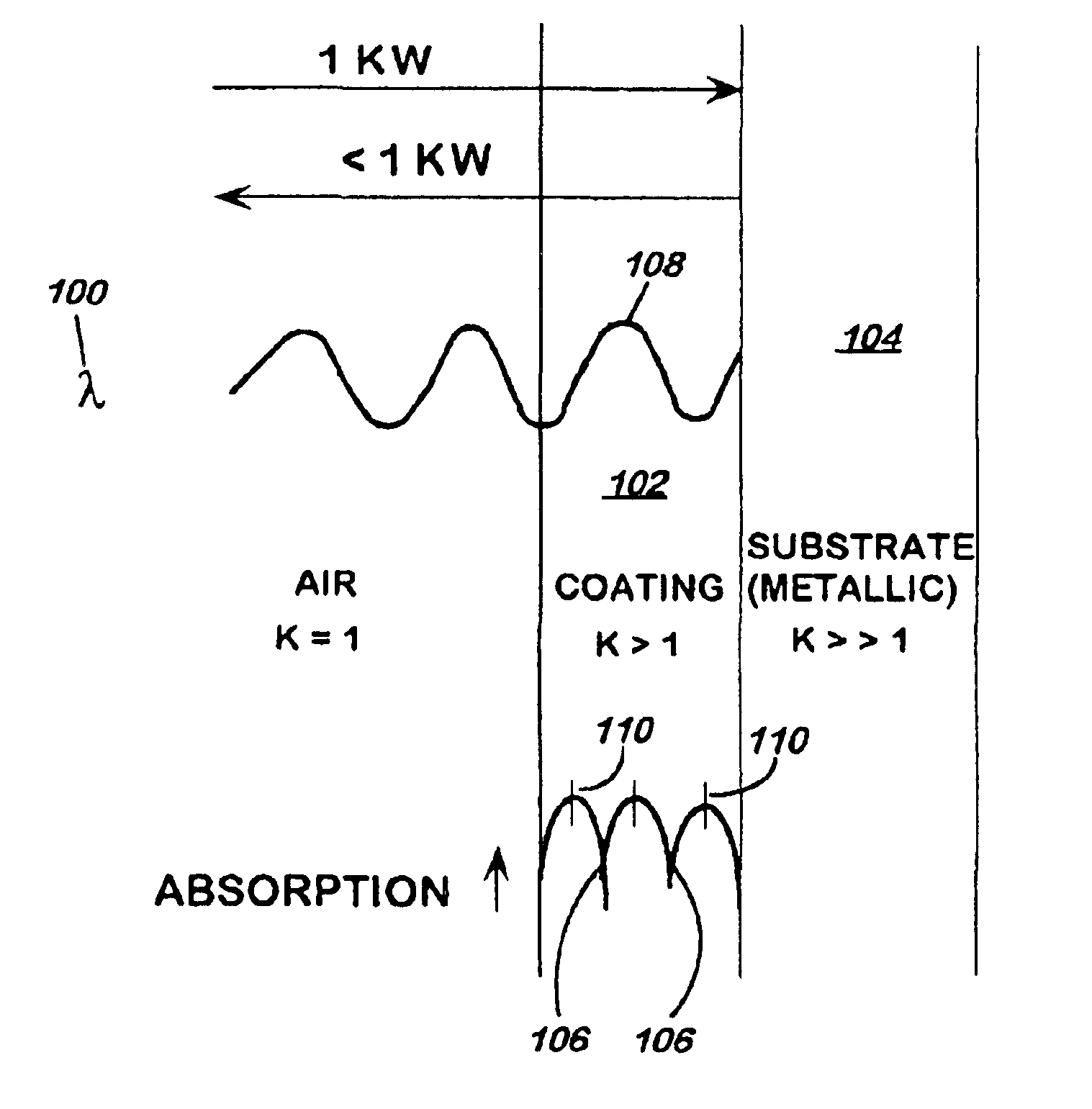
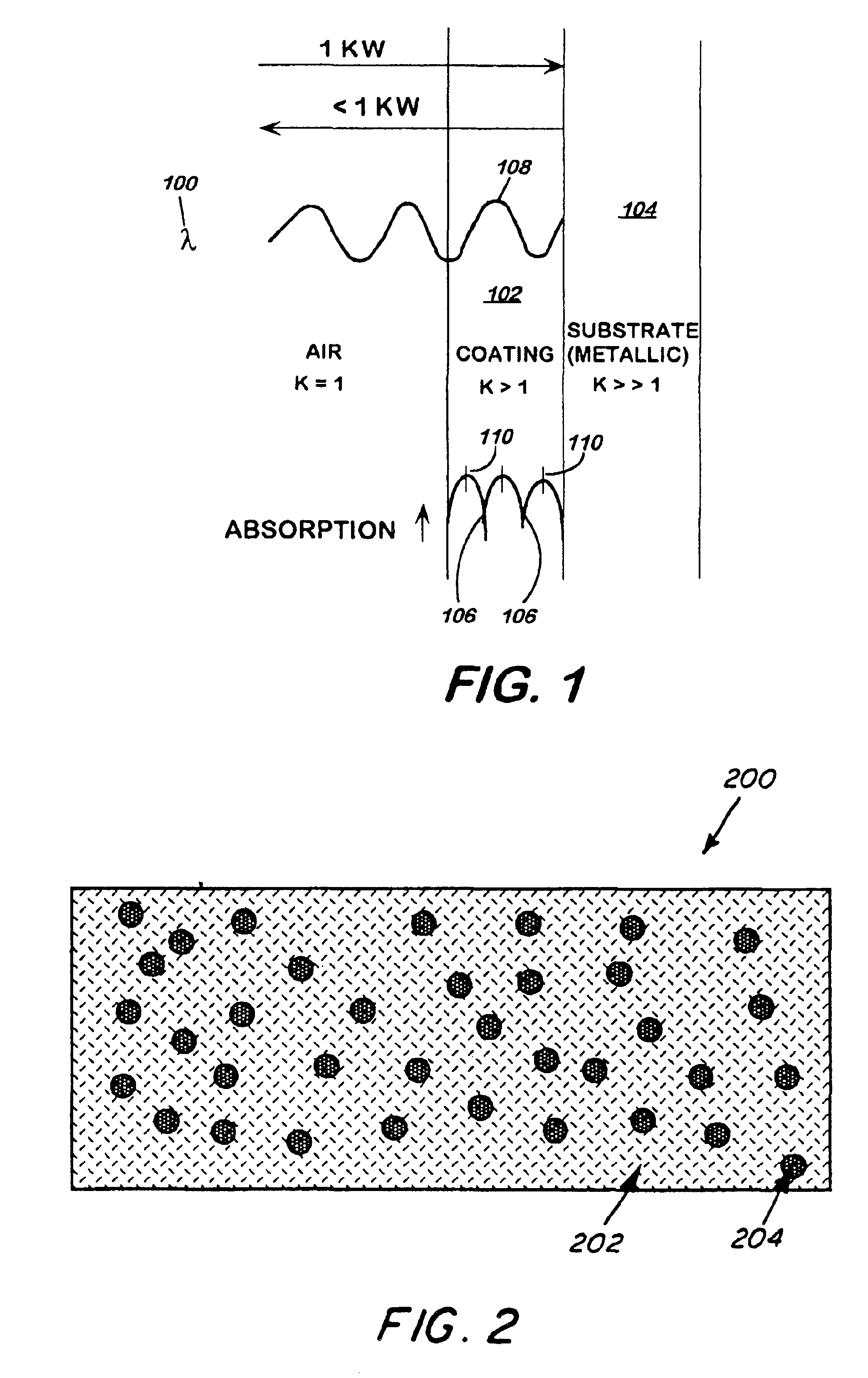
This example demonstrates decomposition of a radar absorbing coating composed of a urethane rubber filled with iron filler particles disposed on a substrate composed of an aluminum foil and a fiberglass reinforced polyester composite by means of high frequency microwave energy. These type of coatings are primarily used on aircraft and are intended to absorb high frequency microwaves of about 30-100 G Hz.

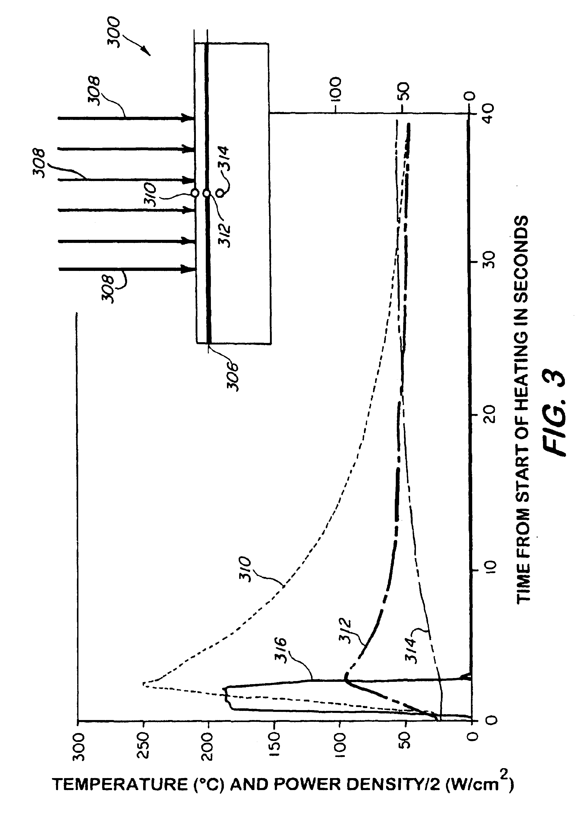
A commercially prepared radar absorbing coating layer composed about 5% by volume iron silicide filler in a urethane rubber about 1 mm thick, was bonded to a fiberglass reinforced polyester composite substrate about 5 mm thick using a high strength two-part epoxy adhesive and an intermediate 12 micron thick aluminum foil ground plane between the urethane coating and the composite. The composite and the aluminum foil comprised the substrate. Thermocouples were placed on the front surface of the coating, between coating and the aluminum foil bonded to the composite, and at a location a...


PUM

PropertyMeasurementUnit
wavelengthaaaaaaaaaa
dielectric constantaaaaaaaaaa
thicknessaaaaaaaaaa

Abstract

Process for removing microwave energy absorbing material disposed on a substrate without thermally and / or mechanically damaging the substrate and with reduced production of volatile matter comprising the steps of directing microwave energy at the coating of sufficient power to damage the coating and removing the damaged coating from the substrate.

Description

This invention pertains to removal of radar absorbing coatings, and other coatings that absorb microwave energy, from a substrate using microwave energy.DESCRIPTION OF RELATED ARTThe processes that have been used to remove radar absorbing material coatings from substrates, particularly from aircraft and ships, include mechanical abrasion; grit blasting, including using dry ice as the abrasive; mechanical scraping; heat lamps; and continuous and pulsed lasers. Conventional mechanical abrasion using conventional abrasives and wire brushes are rather ineffective in removing some of the coatings which are based on rubbery polymers, such as urethanes used for all-around purposes, neoprenes used for their weather resistance, nitrile rubbers used for their fuel and oil resistance, and fluoro-elastomers used for their excellent operating temperature range. In addition, this method produces substantial volume of waste products, including mixtures of abrasives and coating residue, requiring s...

Claims


Application Information

Patent Timeline
Patent Type & Authority Patents(United States)
IPC IPC(8): B08B7/00
CPCB08B7/0035
Inventor LEWIS, III, DAVIDFLIFLET, ARNE W.BRUCE, RALPH W.
Owner THE UNITED STATES OF AMERICA AS REPRESENTED BY THE SECRETARY OF THE NAVY
Why Eureka
Try Eureka