Device for measuring spatial distribution of the spectral emission of an object

a technology of spectral emission and object, which is applied in the direction of instrumentation, spectral investigation, structural/machine measurement, etc., can solve the problems of serious inconvenience and many inconveniences of known techniques

Inactive Publication Date: 2004-10-12
ELDIM
View PDF5 Cites 31 Cited by
  • Summary
  • Abstract
  • Description
  • Claims
  • Application Information

AI Technical Summary

Problems solved by technology

This known technique presents many inconveniences.
Nonetheless, a serious inconvenience has become apparent during usage of this other known technique.
This can be restrictive

Method used


Image

  • Device for measuring spatial distribution of the spectral emission of an object
  • Device for measuring spatial distribution of the spectral emission of an object
  • Device for measuring spatial distribution of the spectral emission of an object

Examples


Embodiment Construction

The aim of the present invention is to remedy these inconveniences.

Its objective is a device which combines the advantages of the technique described in document [3], advantages which have been seen above, with the advantages of spectral measurement.

Certainly, one could envisage (as do documents [2] and [3]), placing a series of selective filters in the path of the luminous signal, making it possible to select a range of wavelengths.

Nonetheless, given that the spread of the visible spectrum is 340 nm (since this visible spectrum ranges from 380 nm to 720 nm) and that the resolution needed for photometric measurements is of the order of 4 nm, 85 successive filters (and 85 successive measurements) would be necessary. Such a technique would therefore lead to long measuring times.

Furthermore, the setting up of 85 filters in the path of a luminous signal is not simple and the cost of these 85 filters is not negligible, since the manufacture of filters with a 4 nm bandpass is especially d...


PUM

PropertyMeasurementUnit
optical Fourier transformaaaaaaaaaa
dispersionaaaaaaaaaa
optical axisaaaaaaaaaa

Abstract

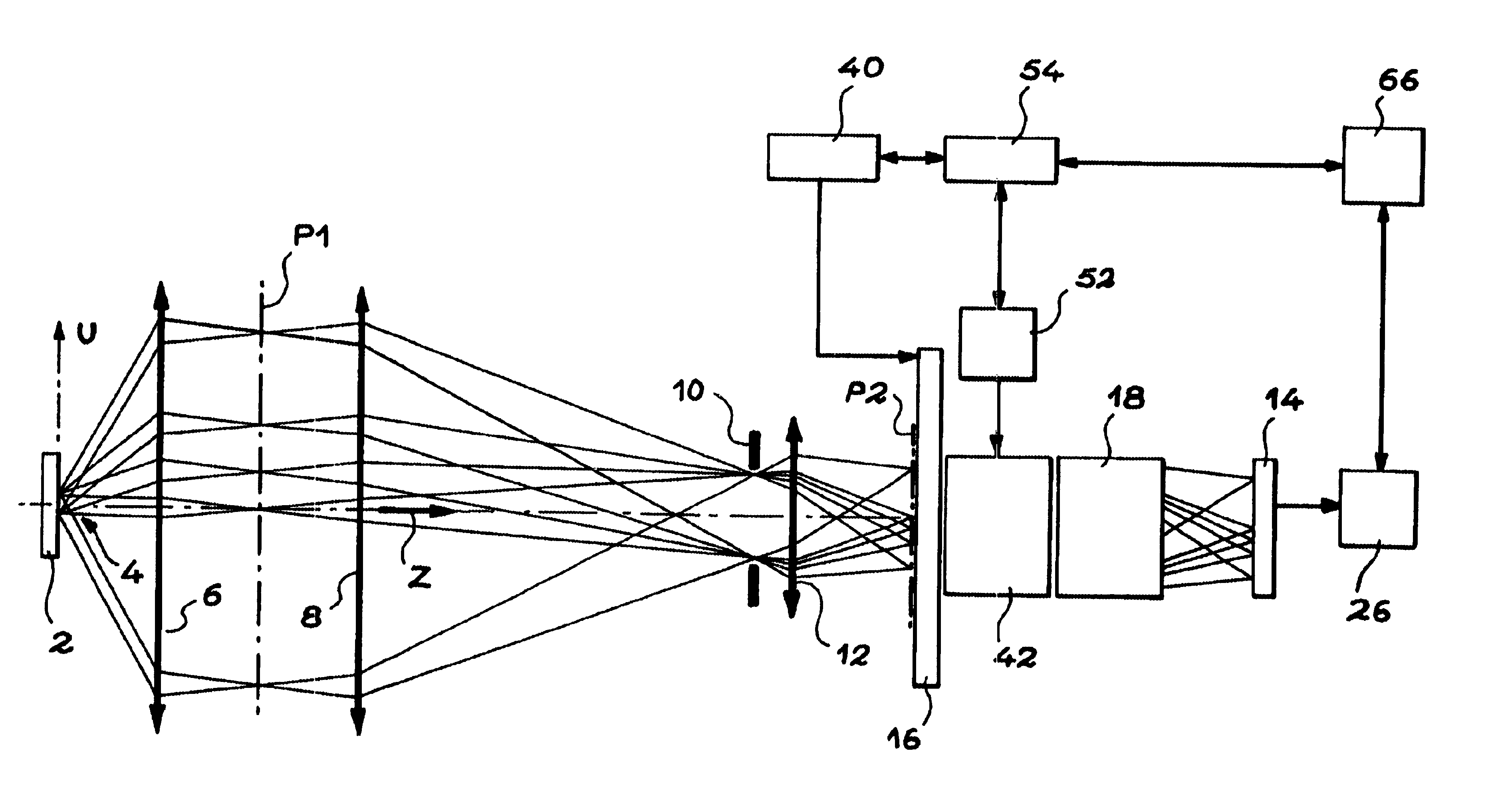
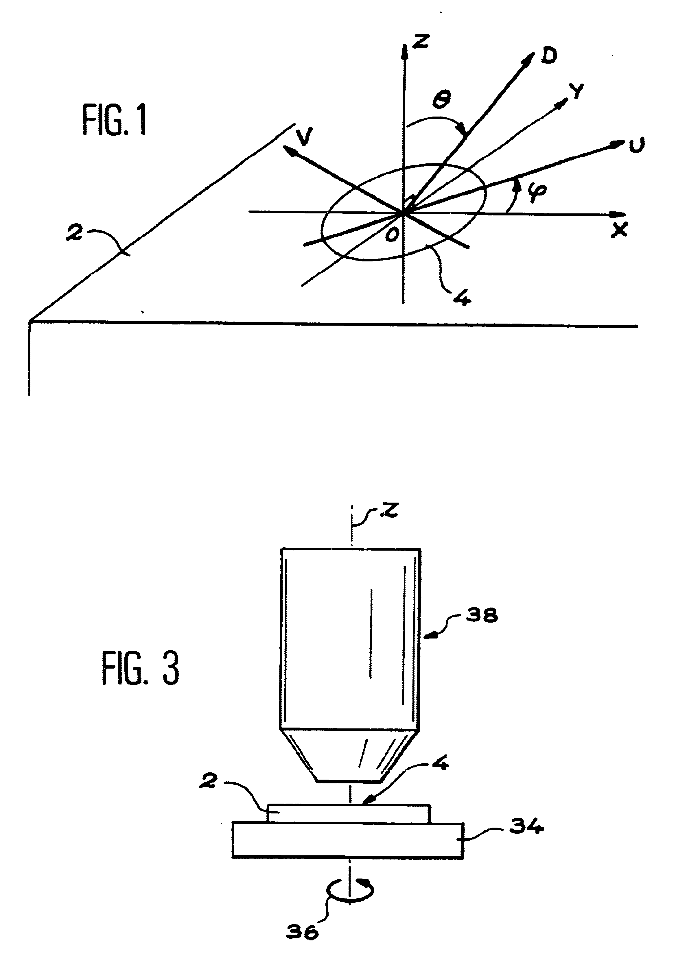
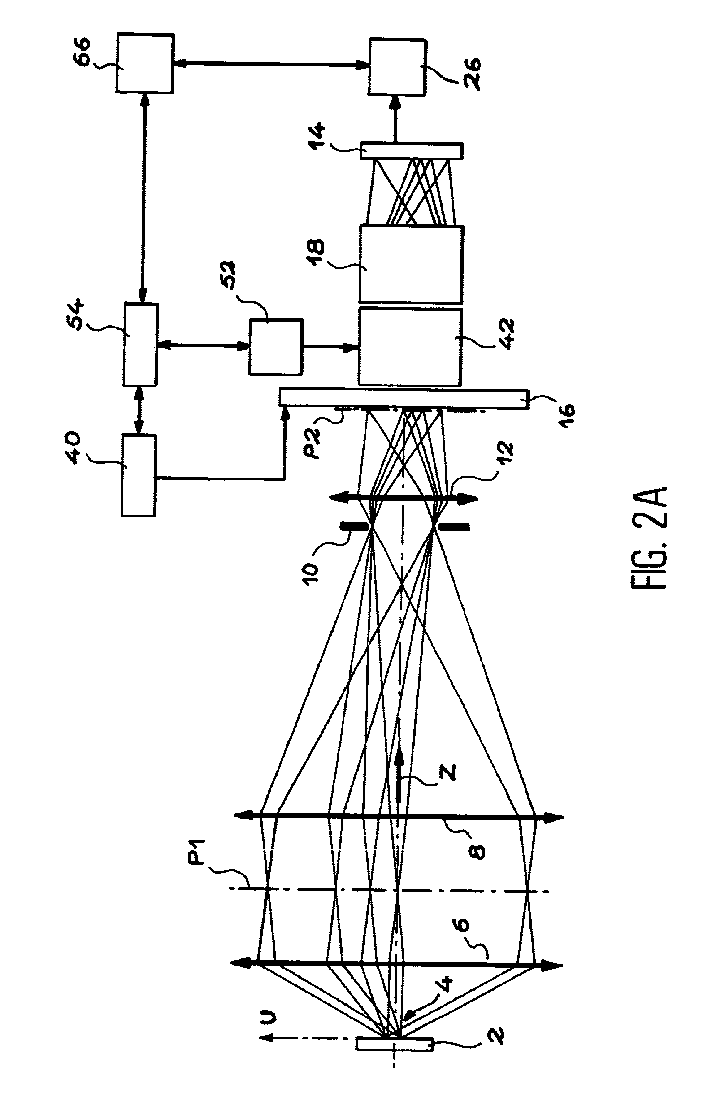
A device for measuring the space distribution of the spectral emission of an object. The device includes a first lens forming in its Fourier plane an image constituting the optical Fourier transform of a zone of the object, a second lens, a diaphragm conjugated optically with the zone by the first and second lenses, a mechanism for selecting a rectilinear portion of the image, a mechanism for dispersion of the light corresponding to this portion, and a sensor receiving the dispersed light. The spectral response of the zone, for each point of the portion, is determined by signals from the sensor. The device is applicable in particular to display screens.

Description

The present invention relates to a device for measuring the space distribution of the spectral emission of an object.It applies in particular to objects such as, for example, projection screens, cathode ray tubes, lighting devices, flat display screens such as liquid crystal screens, plasma screens, electroluminescent screens and microtip screens, as well as reflecting surfaces.STATE OF PRIOR ARTSeveral techniques are already known for measuring the calorimetric specifications of the emission or reflection of light by various objects (for example those mentioned above) as a function of the angle of observation.Reference can be made to the following documents on this subject:[1] EP 0 286 529 A[2] FR 2 729 220 A[3] FR 2 749 388 AIn particular an electromechanical technique is known which consists of moving measuring equipment, such as a photometer, around an object which one wishes to measure. On this subject, reference can be made, for example, to document [1] and in particular to FI...

Claims


Application Information

Patent Timeline
Patent Type & Authority Patents(United States)
IPC IPC(8): G01N21/00G01J3/28G02F1/13G01M11/00
CPCG01J3/2803G02F1/1309G01N21/00G01J3/30G01J5/60G01J2003/282
Inventor LEROUX, THIERRY
Owner ELDIM
Why Eureka
Try Eureka