Electromagnetically-controlled filler spout

a filler spout, electronic technology, applied in the direction of liquid bottling, packaging goods, special packaging, etc., can solve the problems of high manufacturing cost of the filler spout and significant manufacturing constraints

Inactive Publication Date: 2004-11-02
SERAC GROUP
View PDF6 Cites 41 Cited by
  • Summary
  • Abstract
  • Description
  • Claims
  • Application Information

AI Technical Summary

Benefits of technology

A second object of the invention is to propose a filler spout that can easily be adapted to different substances.
In an advantageous version of the invention, the valve member and the magnetic actuator element are mounted in separate-body elements connected together by a quick coupling member, and the elements of the coupling member are separable. It is thus possible to make up different control member and shutter member combinations quickly.
In another advantageous aspect of the invention, the filler spout includes a secondary shutter disposed downstream from the valve member and rigidly connected thereto, and the body has a constriction overlying the secondary shutter, the secondary shutter and the constriction being of dimensions and relative positioning that are appropriate to ensure that while the valve member is closed, the secondary shutter leaves clearance relative to the constriction that is just sufficient to retain a liquid contained in the body between the valve member and the secondary shutter by means of capillarity. This makes it possible without interfering with the closure action of the valve member to maintain a quantity of substance in the filler spout which is sufficient to avoid faulty formation of the jet of substance when the valve member is opened.

Problems solved by technology

The assembly formed in this way is radially rigid so that in order to ensure that the valve member is accurately positioned relative to the valve seat in order to obtain satisfactory leaktightness, it is necessary not only for the valve member to be guided accurately along the axis of the valve seat, but also for the magnetic actuator element to be guided in very precise manner along the axis of the valve member, thereby leading to very significant manufacturing constraints.
These constraints lead to high manufacturing cost for the filler spout.

Method used


Image

  • Electromagnetically-controlled filler spout
  • Electromagnetically-controlled filler spout
  • Electromagnetically-controlled filler spout

Examples


Embodiment Construction

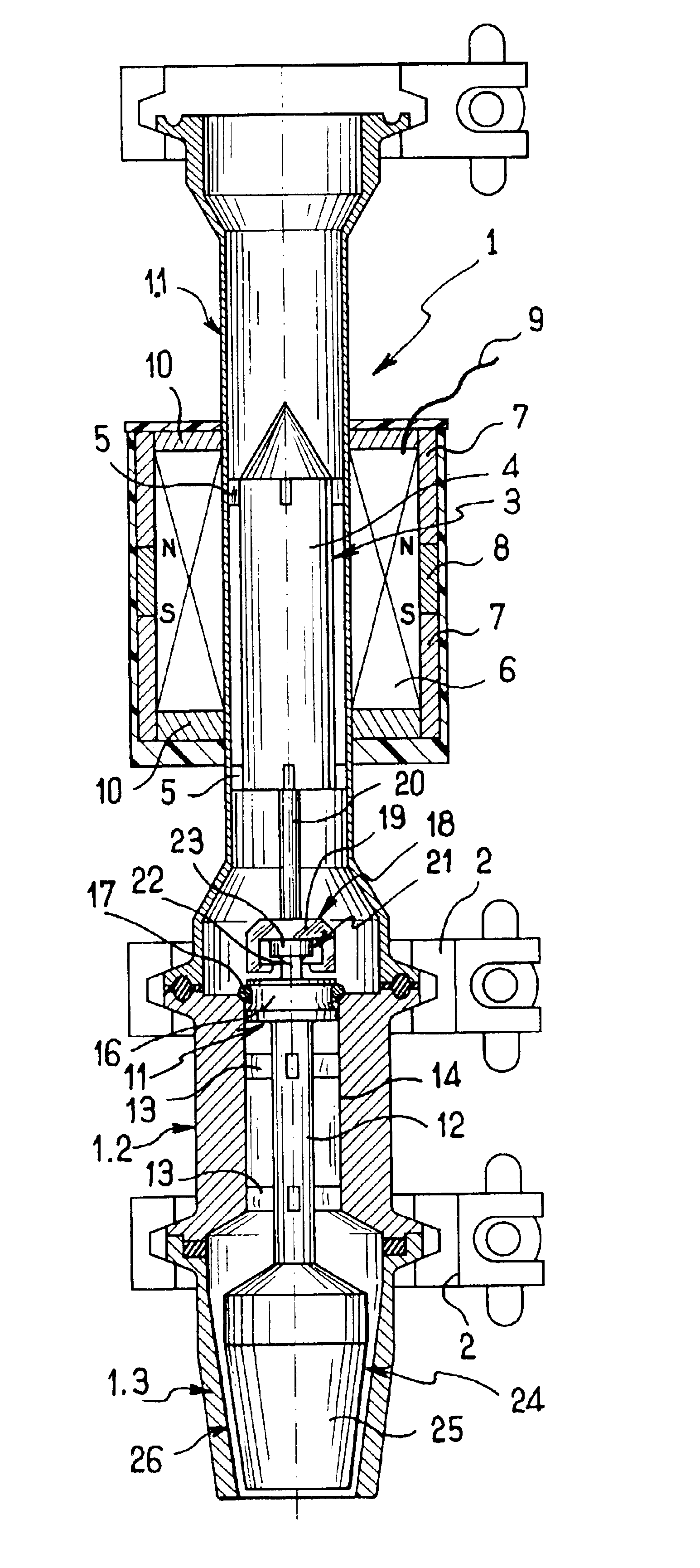
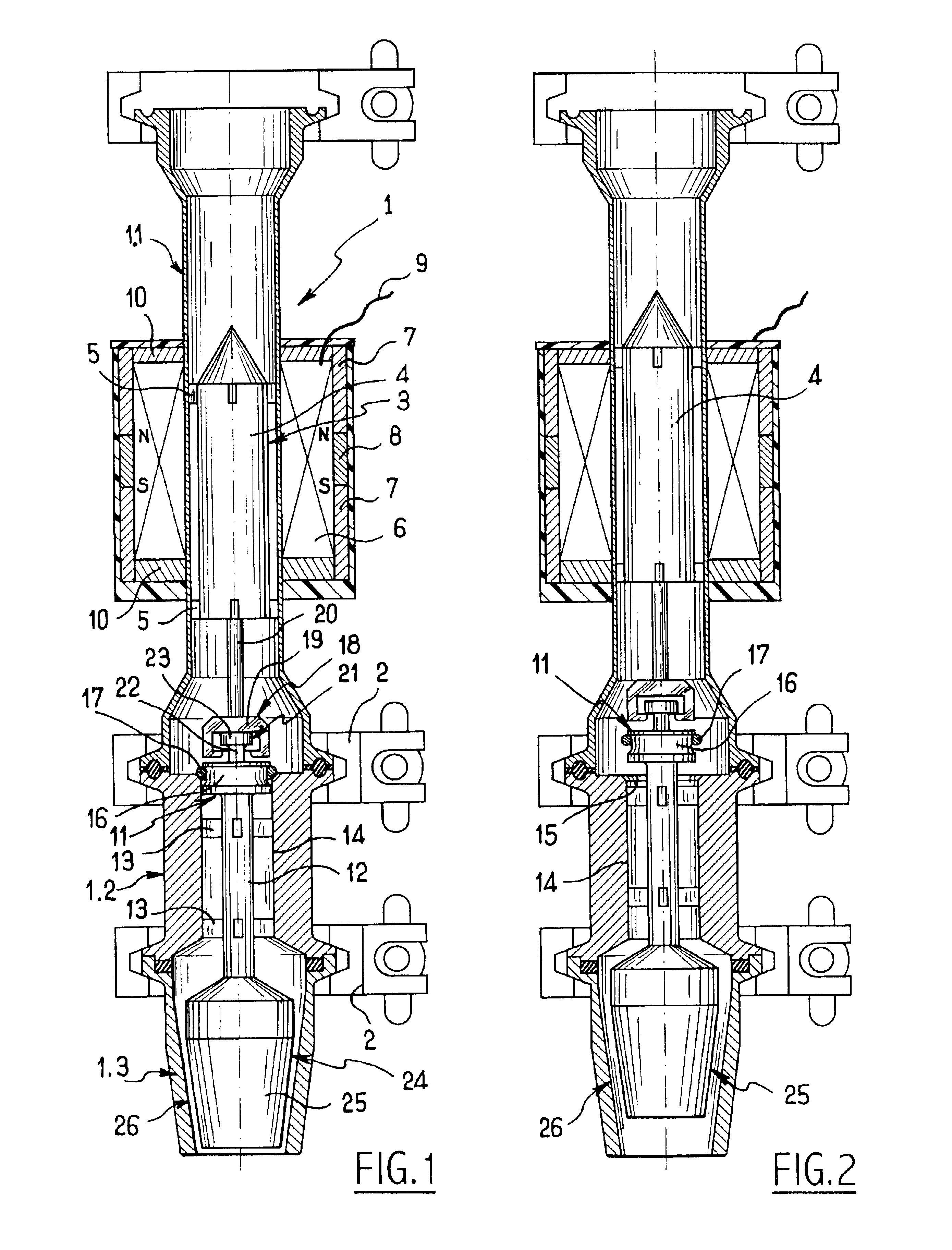
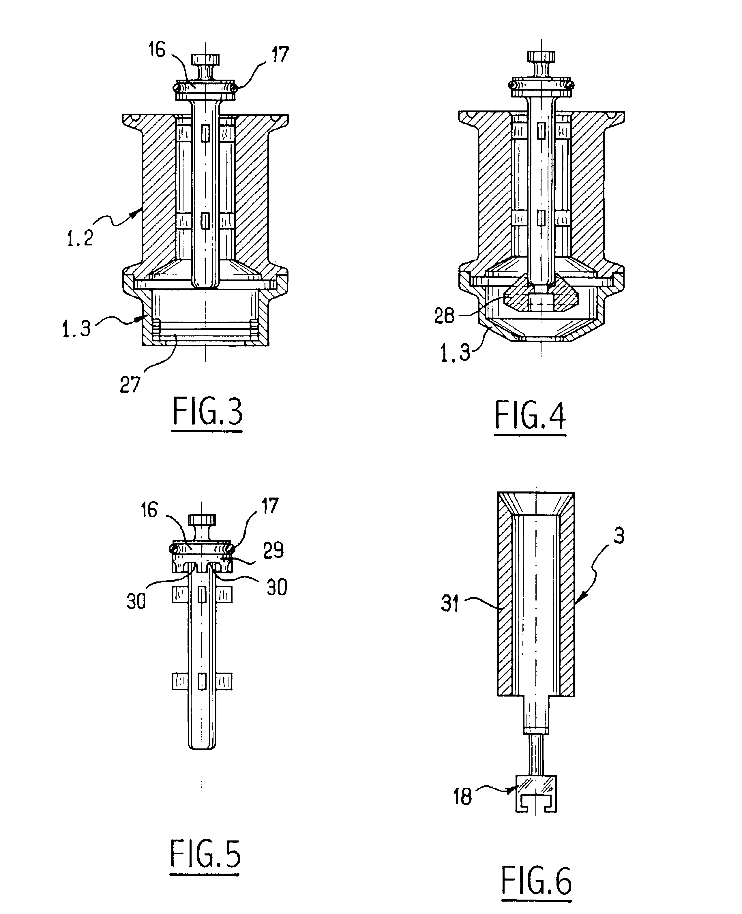
With reference to FIGS. 1 and 2, the filler spout of the invention comprises a tubular body 1 made up of three body elements 1.1, 1.2, and 1.3 interconnected by quick coupling members 2 and respectively containing the elements performing the control, shut-off, and outlet delivery or secondary shut-off functions of the filler spout of the invention.

The control function is performed by a magnetic actuator element 3 mounted to slide in body element 1.1. In the embodiment of FIG. 1, the magnetic actuator element 3 comprises a solid magnetic core 4 provided at its periphery with guide fins 5 which provide accurate guidance for the core 4 inside the body element 1.1 while allowing a substance to flow between the core 4 and the inside face of the body element 1.1. The body element 1.1 is made of non-magnetic material, and it is surrounded by a coil 6 connected by a feed wire 9 to power supply means (not shown) for forming an electromagnetic actuator device.

In the embodiment shown, the coil...


PUM

PropertyMeasurementUnit
permanent magnetic fieldaaaaaaaaaa
magneticaaaaaaaaaa
weightaaaaaaaaaa

Abstract

The filler spout comprises a tubular body having mounted therein a valve member and a magnetic actuator element connected to the valve member via a coupling member comprising two elements that are coupled to each other via a coupling that includes radial clearance.

Description

The present invention relates to an electromagnetically-controlled filler spout.A filler spout known in particular from document WO 01 / 40098 comprises a tubular body having mounted therein a valve member extending over a valve seat, and a magnetic actuator element associated with a coil outside the tubular body and connected to the valve member via an axial coupling member. The assembly formed in this way is radially rigid so that in order to ensure that the valve member is accurately positioned relative to the valve seat in order to obtain satisfactory leaktightness, it is necessary not only for the valve member to be guided accurately along the axis of the valve seat, but also for the magnetic actuator element to be guided in very precise manner along the axis of the valve member, thereby leading to very significant manufacturing constraints. In particular, the valve member and the magnetic actuator element need to be mounted accurately on the same axis as each other, and when the...

Claims


Application Information

Patent Timeline
Patent Type & Authority Patents(United States)
IPC IPC(8): B67C3/28B67C3/26B67C3/02
CPCB67C3/26B67C3/281Y10S141/01
Inventor GRAFFIN, ANDRE
Owner SERAC GROUP
Why Eureka
Try Eureka