
Atomic oscillator

a technology of atomic oscillators and oscillators, which is applied in the field ofatomic oscillators, can solve the problems of complicated mechanism structure, high price, and difficulty of atomic oscillators

Inactive Publication Date: 2004-11-02
FUJITSU LTD
View PDF3 Cites 17 Cited by
  • Summary
  • Abstract
  • Description
  • Claims
  • Application Information

AI Technical Summary

Problems solved by technology

It is difficult for the atomic oscillator using the prior art cavity resonator as mentioned above to meet the market demands as follows:
For this reason, the structure of the mechanism becomes complicated and the price becomes expensive.
Also, the adjustment of the resonance frequency is necessary, and the cost increases in proportion to adjustment man-hours etc.
Furthermore, in order to excite the resonator, a mechanical antenna or a probe becomes necessary, so that the mechanism becomes complicated even in this point, which causes a cost increase.
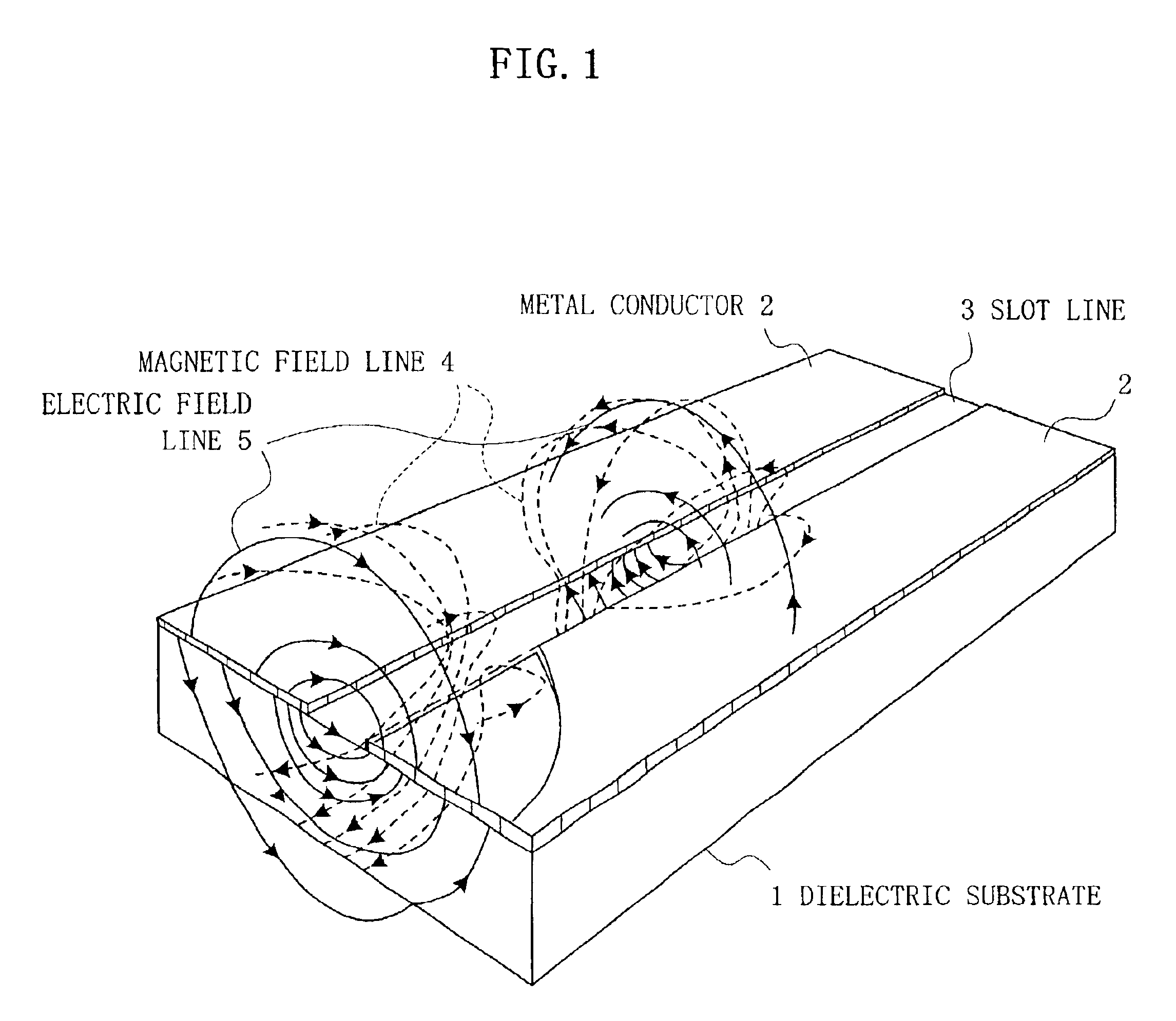
However, since it is characterized in that the magnetic field does not influence the outside as mentioned above, the application thereof to the atomic oscillator is difficult.
This means that the passage loss is large, and unnecessary coupling of a crosstalk or the like is required to be prevented, so that it is difficult to use the slot line for a transmission line.

Method used


Image

  • Atomic oscillator
  • Atomic oscillator
  • Atomic oscillator

Examples


Embodiment Construction

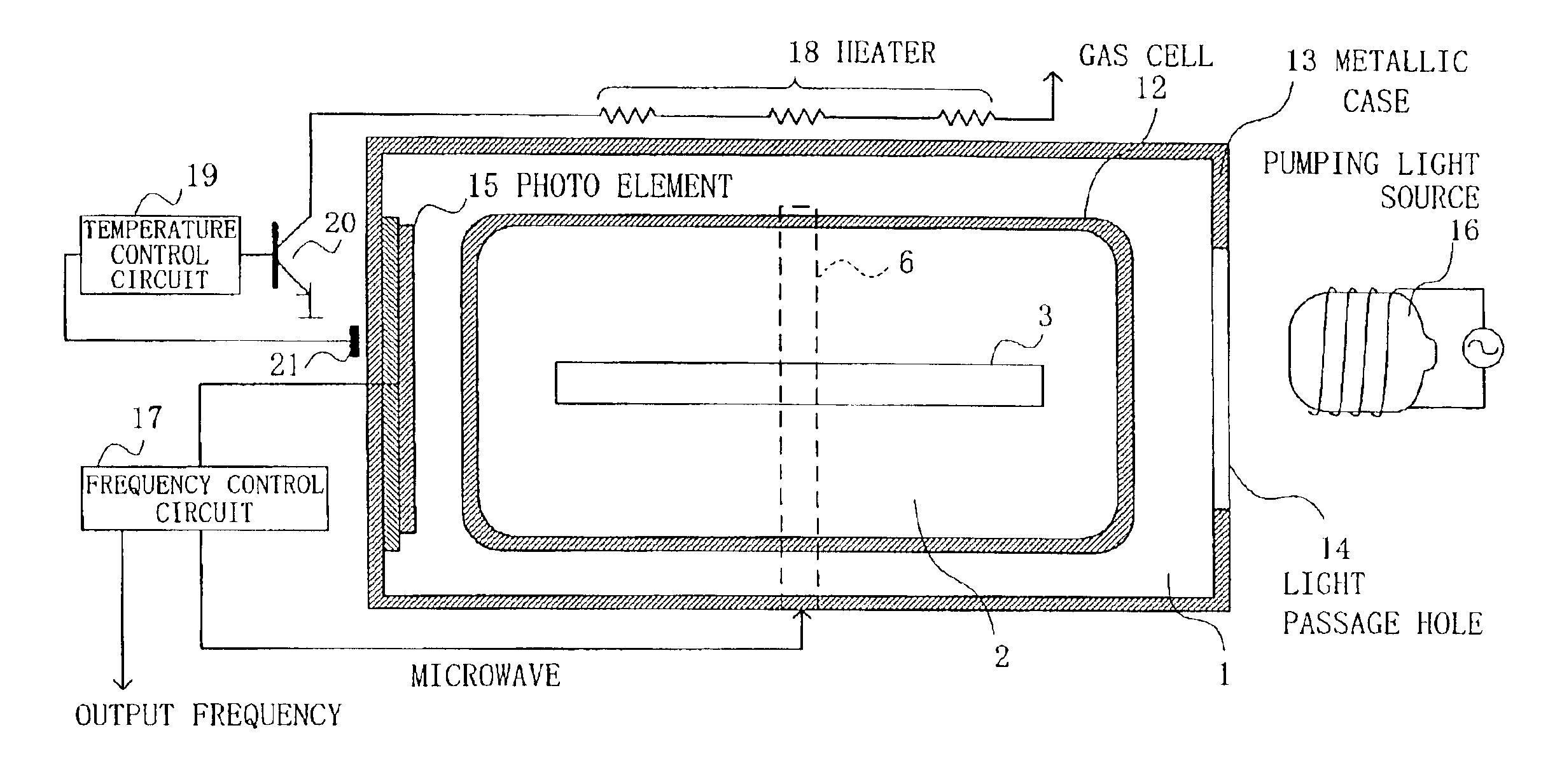
FIGS. 4A-4C show an embodiment (1) of an atomic oscillator according to the present invention, in which FIG. 4C shows a perspective view, FIG. 4A shows a sectional view as cut along X-Y plane in FIG. 4C, and FIG. 4B shows a sectional view as cut along X-Z plane in FIG. 4C.

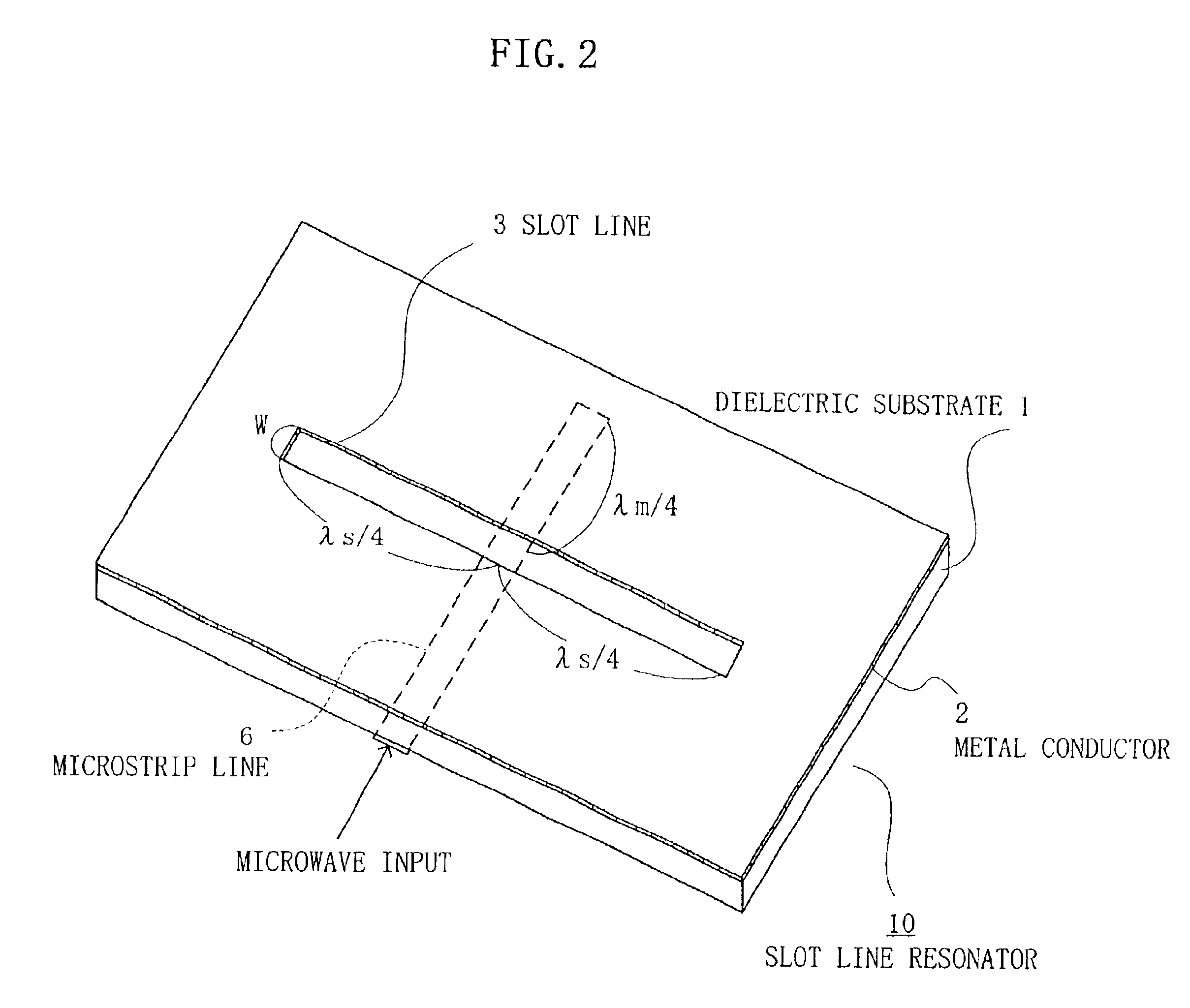
In this embodiment, as having been shown in FIG. 2, a cross junction is formed with the slot line 3 and the microstrip line 6, connected to an external coupling circuit, on both sides of the dielectric substrate 1, which is easily formed by a conventionally well-known photo etching technique.

A gas cell 12 that is a light-permeable container in which rubidium atoms 11 are enclosed is mounted, as shown in FIGS. 4A-4C, in an area where a resonant magnetic field of the slot line resonator 10 is distributed. While this embodiment has a form that the gas cell 12 is placed on the slot line 3 is adopted considering a tight coupling with the magnetic field, if this coupling with the magnetic field is close enough, the gas c...


PUM


Abstract

In an atomic oscillator of an optical pumping system, a slot line resonator, as a microwave resonator, is arranged in a portion where atoms are excited. The slot line resonator forms a microstrip line inputting microwaves so as to be orthogonal to a slot line with a dielectric substrate being sandwiched therebetween. A container in which the atoms are enclosed is mounted on the slot line resonator, and the slot line resonator and the container are covered with a metallic case having a pumping light passage hole and a photo element.

Description

1. Field of the InventionThe present invention relates to an atomic oscillator, and in particular to a passive-type atomic oscillator of an optical pumping system.Recently, digital networking of information has been advanced, whereby a clock source with high accuracy / high stability becomes indispensable. While an atomic oscillator such as a rubidium atomic oscillator draws attention as the clock source, downsizing / slimming is expected for mounting form on a system.2. Description of the Related ArtFIG. 7 schematically shows a rubidium atomic oscillator having a light-microwave resonator as known in the prior art.This atomic oscillator is composed of a pumping light source 16, a cylindrical cavity resonator 40 having light passage holes (apertures) 15a and 15b for receiving a pumping light from the light source 16, a doughnut-shaped dielectric 41 contained in the resonator for downsizing the cavity resonator 40, a gas cell 42 for enclosing rubidium atoms further contained in the diele...

Claims


Application Information

Patent Timeline
Patent Type & Authority Patents(United States)
IPC IPC(8): G04F5/00G04F5/14H01S1/06H03L7/26
CPCG04F5/14
Inventor MATSUURA, HIDEYUKIATSUMI, KENKOYAMA, YOSHITOSAKAI, MINORU
Owner FUJITSU LTD
Learn More