Stabilized frequency-converted laser system

a laser system and frequency conversion technology, applied in the direction of laser details, instruments, electrical equipment, etc., can solve the problems of dpss laser frequency conversion output power degrade, etc., to achieve the effect of improving the stability of the laser system

a laser system and frequency conversion technology, applied in the direction of laser details, instruments, electrical equipment, etc., can solve the problems of dpss laser frequency conversion output power degrade, etc., to achieve the effect of improving the stability of the laser system

US20060072635A1Active Publication Date: 2006-04-06COHERENT INC

Image

  • Stabilized frequency-converted laser system
  • Stabilized frequency-converted laser system
  • Stabilized frequency-converted laser system

Examples


Embodiment Construction

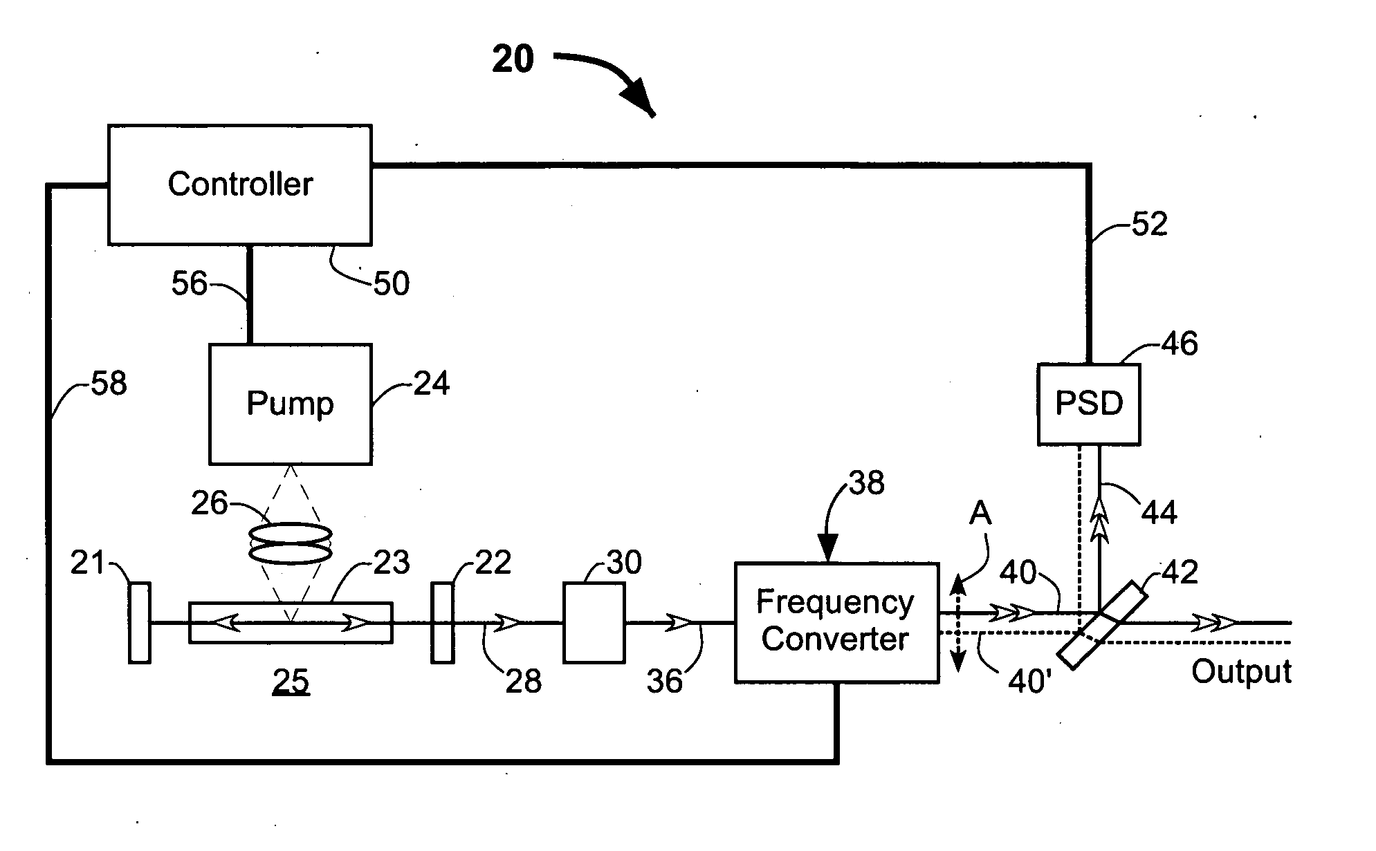
[0026] Referring now to the drawings, wherein like features are designated by like reference numerals, FIG. 1 schematically illustrates one preferred embodiment 20 of a frequency-converted laser system in accordance with the present invention. Laser system 20 includes a laser resonator 25 formed between mirrors 21 and 22. Laser resonator 25 includes a gain medium 23 energized by a pump system 24. Pump system 24 is arranged in optical communication with the gain medium 23 through a pump delivery apparatus 26. In response to the energizing of the gain medium, laser resonator 25 generates and delivers a fundamental beam 28 having a fundamental wavelength.

[0027] Pump delivery apparatus 26 is depicted in FIG. 1, for convenience of illustration, as supplying energy to gain medium 23 from the side of the fundamental beam-path (side-pumping). Side-pumping should not be considered as limiting the present invention since pump light can also be delivered predominantly along the axis of propag...


PUM


Abstract

A laser system includes an optically pumped laser resonator that produces a fundamental-wavelength beam. A temperature-tuned frequency converter outside the laser resonator converts a portion of the fundamental-wavelength beam to a frequency-converted beam. The frequency converter includes at least one temperature-tuned optically nonlinear crystal. The power and position of the frequency-converted beam are dependent on the temperature of the optically nonlinear crystal and the optical pumping power. The power and position of the frequency-converted beam are monitored. The temperature of the optically nonlinear crystal is adjusted to maintain the frequency-converted beam at a predetermined position. The optical pump power is adjusted to maintain the power of the frequency-converted beam at a predetermined level.

Description

TECHNICAL FIELD OF THE INVENTION [0001] The present invention relates in general to the stabilization of the output of a laser system. The invention relates in particular to stabilizing the output of a diode-laser pumped, solid-state, externally frequency-converted laser system. DISCUSSION OF BACKGROUND ART [0002] High-precision laser machining applications can impose stringent performance requirements on laser systems. Laser drilling of the numerous small via-holes commonly incorporated in multi-layer printed circuit boards to provide inter-layer connections exemplifies such an application. Accurate placement and consistent dimensions of the laser-drilled holes must be maintained throughout a production cycle that may include many thousands or even millions of nominally identical holes. Consequently, to be considered suitable for via-drilling, a laser system should exhibit near-constant time-averaged output power and steady beam pointing during extended periods of operation. A diod...

Claims


Application Information

Patent Timeline
06 Apr 2006
Publication
US20060072635A1
IPC
H01S3/10; H01S3/13
CPC
G02F2001/3546; H01S3/0014; H01S3/109; H01S3/1305; H01S3/1312; H01S3/1611; H01S3/1673; G02F1/3546
Inventors
WANG, CHARLES XIAOYI