Optical pumping magnetometer and magnetic sensing method

a technology of optical pumping magnetometer and magnetic sensing method, which is applied in the direction of magnetic field measurement using magneto-optic devices, magnetic field measurement using magnetic resonance, etc., can solve the problem of not and achieve the effect of improving the response of the magnetometer and highly sensitive measurements of magnetic signals

Active Publication Date: 2016-01-26
CANON KK
View PDF4 Cites 42 Cited by
  • Summary
  • Abstract
  • Description
  • Claims
  • Application Information

AI Technical Summary

Benefits of technology

[0009]An object of the present subject matter is, in view of the problem described above, to provide an optical pumping magneto meter and a magnetic sensing method which make it possible to improve the response of the magnetometer with respect to a magnetic field that varies with a period shorter than the transverse relaxation time of electron spin of an alkali metal atom and make highly sensitive measurements of magnetic signals when the magnetic field is measured with variation in Larmor frequency.
[0017]wherein detuning as a difference between Larmor frequency determined from the static magnetic field and a frequency of the driving current input into the oscillating magnetic field application coil is configured to be set within a predetermined range with respect to a measured magnetic field by adjusting the static magnetic field or the oscillating magnetic field, so as to improve response of the optical pumping magnetometer.
[0024]setting detuning as a difference between a Larmor frequency determined from the static magnetic field and a frequency of a driving current input into a coil to which the oscillating magnetic field is applied, within a predetermined range with respect to a measured magnetic field by adjusting the static magnetic field or the oscillating magnetic field, so as to improve response of the optical pumping magnetometer.

Problems solved by technology

However, the conventional example has a problem that the response of the magnetometer is not improved even when the transverse relaxation time is increased in the case of measuring a variable magnetic field with a shorter variation period of the magnetic field generated from the object to be measured, as compared with the transverse relaxation time of the electron spin of the alkali metal vapor.

Method used


Image

  • Optical pumping magnetometer and magnetic sensing method
  • Optical pumping magnetometer and magnetic sensing method
  • Optical pumping magnetometer and magnetic sensing method

Examples


example embodiment 1

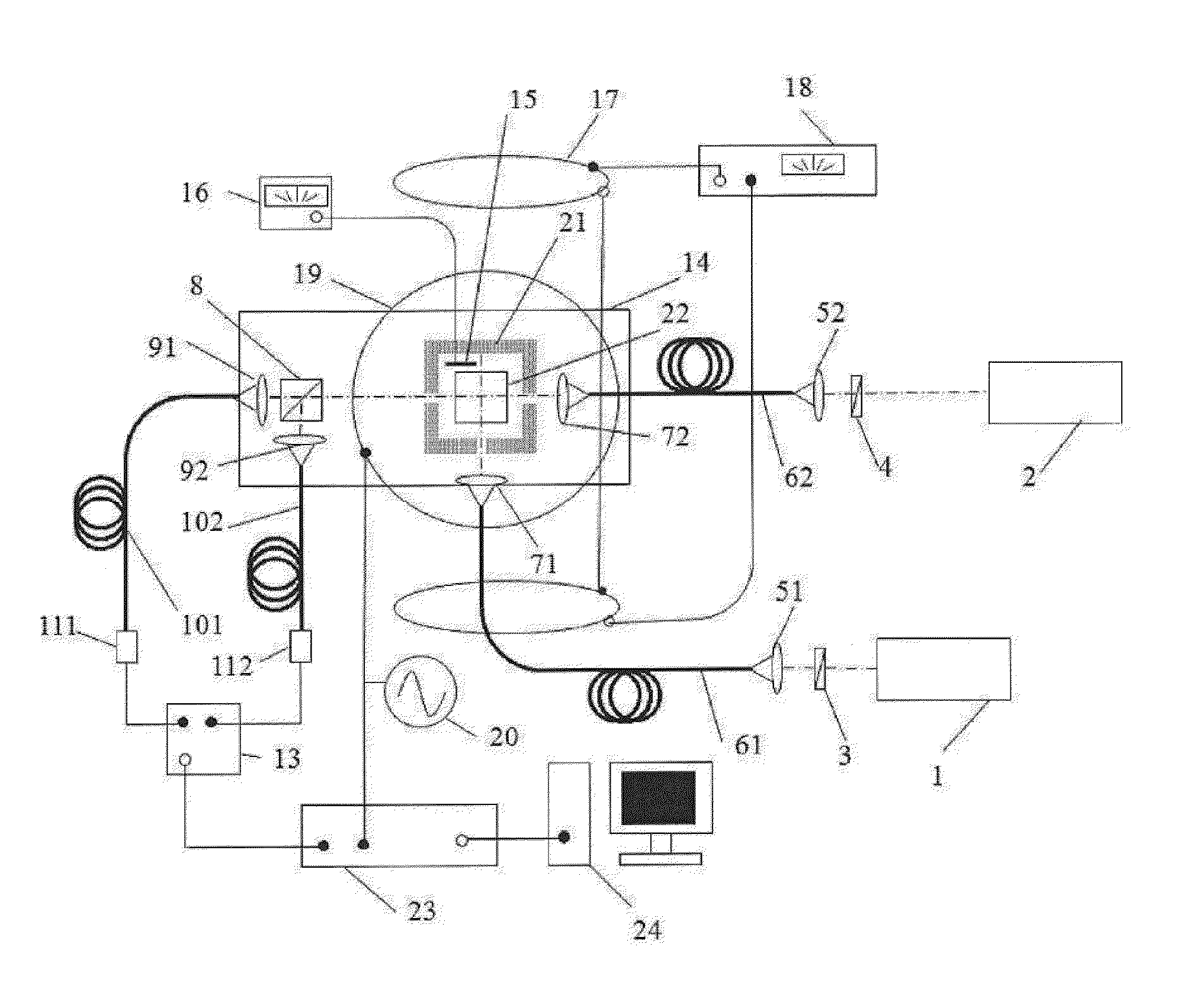
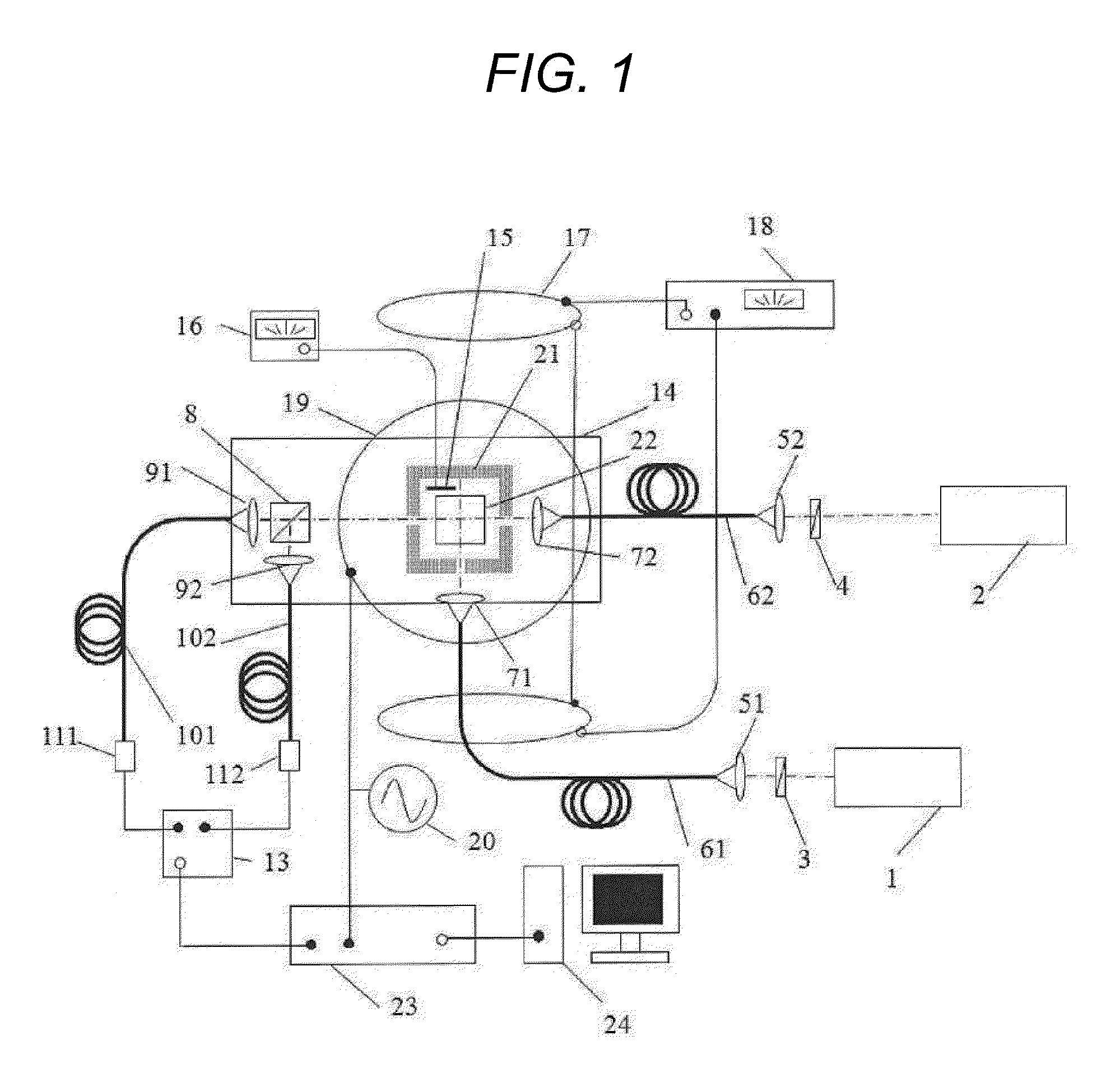
[0039]As example embodiment 1, a configuration example of an optical pumping magnetometer for measuring a magnetic field with variation in Larmor frequency through the application of the present subject matter will be described with reference to FIG. 1.

[0040]In the present example embodiment, with potassium as an alkali metal atom, optical pumping is carried out through the use of D1 transition of the potassium.

[0041]It is to be noted that D2 transition of the potassium may be used for optical pumping.

[0042]In addition, the alkali metal atom is not limited to potassium, but may be rubidium or cesium.

[0043]Potassium atoms, helium as a buffer gas for relaxing collisions between the potassium atoms and a glass wall of a glass cell 22, and nitrogen for quench are enclosed within the glass cell 22. The buffer gas is not limited to helium, but may be neon or argon.

[0044]In order to obtain a sufficient amount of potassium metal vapor in the glass cell, the glass cell 22 is heated up to on ...

example embodiment 2

[0145]As example embodiment 2, a configuration example of applying an optical pumping magnetometer according to the present subject matter to a biomagnetic measurement will be described with the reference to FIG. 7.

[0146]In the biomagnetic measurement according to the present example embodiment, as shown in FIG. 7, a weak magnetic field generated by brain activity or the like from a head 251 of a subject is measured with a magnetic sensor unit 211 and a magnetic sensor unit 212. The magnetic sensor unit 211 and the magnetic sensor unit 212 as well as the subject are placed in a magnetic shield 231 for shielding against geomagnetism and magnetic fields in external environments.

[0147]A sensor electric unit 221 is connected with an optical fiber or cable via an opening provided in the magnetic shield 231 to the magnetic sensor unit 211.

[0148]In addition, a signal generator 201 that generates a driving current for applying an oscillating magnetic field is connected to the sensor electri...


PUM


Abstract

An optical pumping magnetometer is provided that is capable of improving the response of the magnetometer with respect to a magnetic field that varies with a period shorter than the transverse relaxation time of electron spin of an alkali metal atom.

Description

BACKGROUND[0001]1. Field[0002]The present subject matter relates to an optical pumping magnetometer and a magnetic sensing method.[0003]2. Description of Related Art[0004]As highly sensitive magnetic detection methods, optical pumping magnetometers have been proposed which use electron spin of alkali metal vapor.[0005]Applied Physics B has disclosed an optical pumping magnetometer for detecting a magnetic field with the use of variation in Larmor frequency in a glass cell containing cesium.[0006]In this optical pumping magnetometer, the electron spin motion of cesium vapor is caused by the oscillating magnetic field applied from an excitation coil, and changes the absorption of laser light passing depending on the orientation of spin polarization. The intensity of the transmitted laser light is detected by a photo-detector to obtain a signal that changes at the same frequency as the oscillating magnetic field. Attention is focused on the phase difference between the signal from the ...

Claims


Application Information

Patent Timeline
Patent Type & Authority Patents(United States)
IPC IPC(8): G01R33/32G01R33/26G01R33/032
CPCG01R33/26
Inventor KOBAYASHI, TETSUOTERAO, AKIRA
Owner CANON KK
Why Eureka
Try Eureka