Geometric motion analysis

Inactive Publication Date: 2004-11-09
SLICE DENNIS E +1
View PDF8 Cites 37 Cited by
  • Summary
  • Abstract
  • Description
  • Claims
  • Application Information

AI Technical Summary

Problems solved by technology

The fitting and associated constraints, however, impose a certain structure on the data that cannot be ignored during subsequent analyses.
For many questions, though, such "static" analyses are inadequate.
For this data, the application of standard exploratory methods fail to provide the desired results.
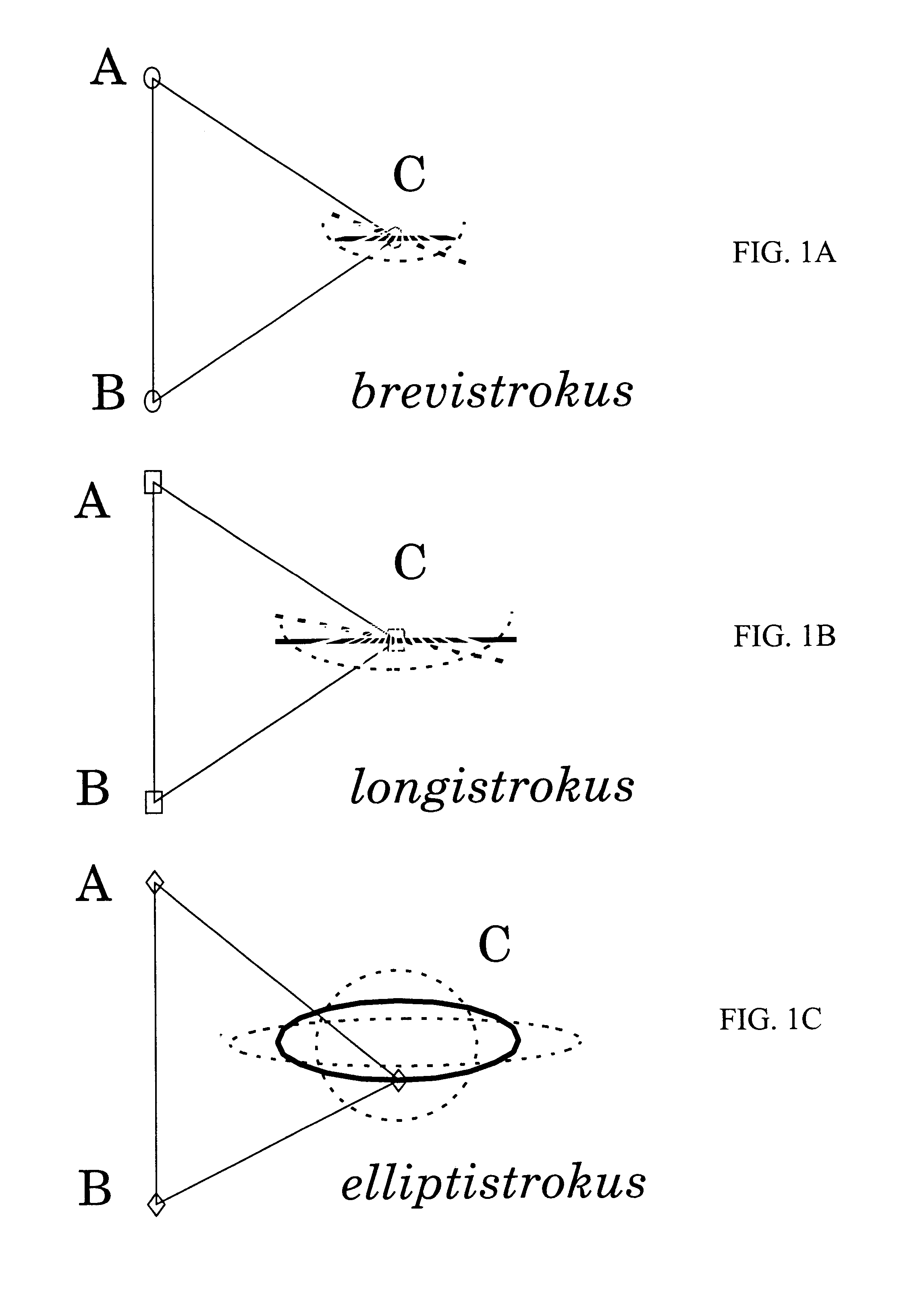
The less clear result for the third individual of elliptistr

Method used


Image

  • Geometric motion analysis
  • Geometric motion analysis
  • Geometric motion analysis

Examples


Embodiment Construction

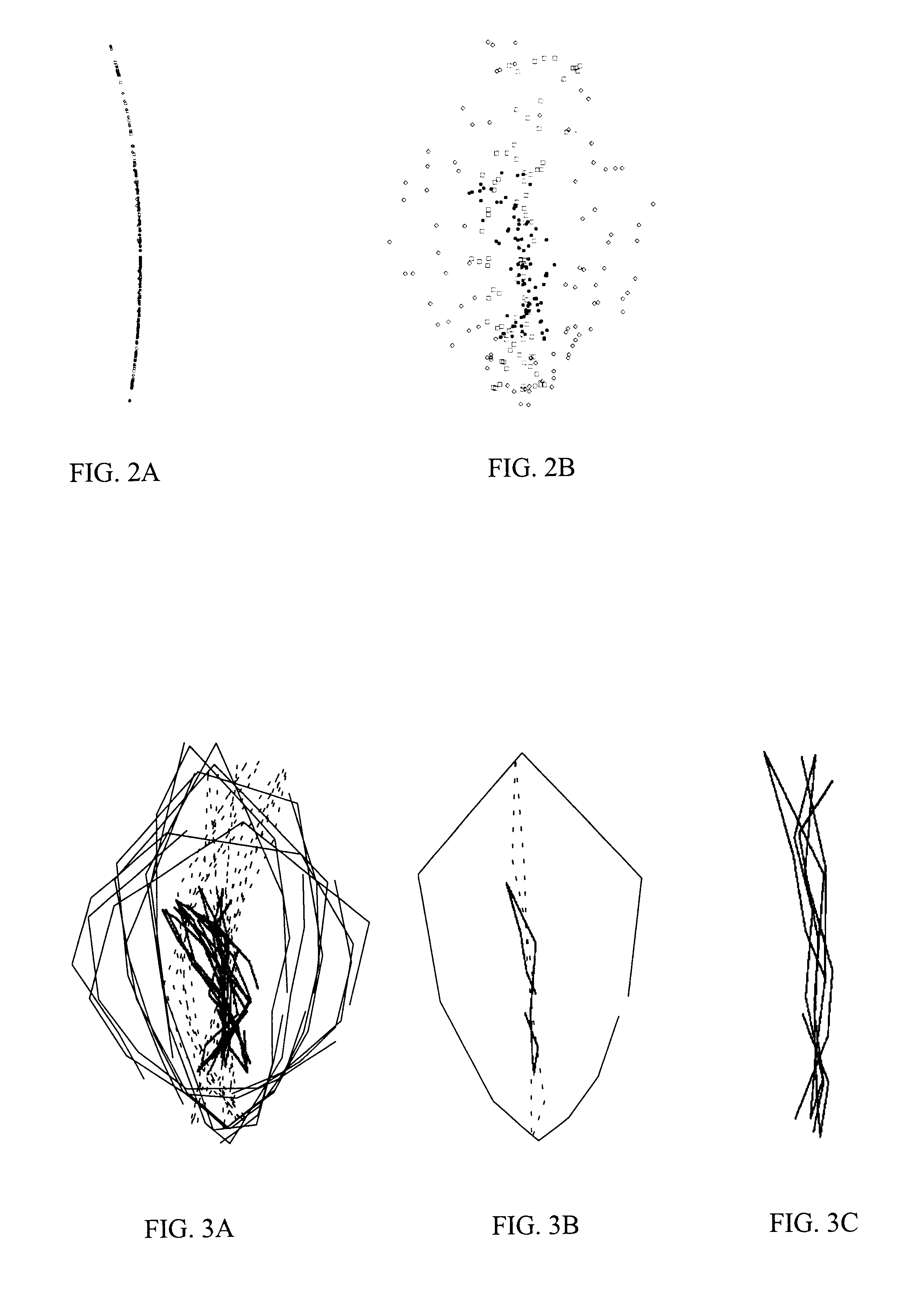
FIG. 9A illustrates a partial geometric motion analysis of the present invention with real motion data. FIG. 9A shows an individual about to initiate a jump with reflective markers (landmarks) that are automatically tracked during the execution of the motion. To take advantage of the analyses provided by existing software, we focus on three of these, those indicating the location of the hip, knee, and ankle. FIG. 9B shows the raw positions of these three points during one jump by one individual. FIG. 9C shows the superimposition of the vertices of triangles formed by the hip, knee, and ankle using standard methods of geometric morphometric analysis (a Generalized Procrustes Analysis). Jumps were sampled (coordinates of the knee, hip, and ankle were recorded) at a rate of 120-175 times per jump.

Unlike FIGS. 9A-C, that show the positions of points in physical space (scaled, translated, and rotated in FIG. 9C), FIGS. 9D-9F show trajectories of shape change through shape space (which is...


PUM


Abstract

A method for geometrically analyzing motion having the steps of: choosing a set of points having at least three individual points to define a single realization of a motion; sequentially collecting Cartesian coordinates of the set of points at different times during the motion from a start point to an end point; treating the collection of sets of points as a sample of the motion; and transforming the sets of points at the different times to a common coordinate system thereby defining a trajectory of the motion. In a preferred implementation of the method of the present invention, the method further has the steps of: choosing a set of points having at least three individual points to define a single realization of a motion; sequentially collecting Cartesian coordinates of the set of points at different times during the motion from a start point to an end point; treating the collection of sets of points as a sample of the motion; transforming the sets of points at the different times to a common coordinate system thereby defining a trajectory of the motion; and calculating elliptic Fourier coefficients describing the trajectory of the motion independent of any difference in the spacing of the different times.

Description

1. Field of the InventionThe field of art to which this invention relates is motion analysis, and more particularly to geometric methods for analyzing shape changes resulting from repetitive motions using Elliptic Fourier Analysis (EFA).2. Description of the Related ArtGeometric morphometric methods characterize the shape of a configuration of landmarks in such a way as to retain all of the relative spatial information encoded in the original data throughout an analysis (See, Slice, D. E., F. L. Bookstein, L. F. Marcus, and F. J. Rohlf. 1996. A glossary for geometric morphometrics. In L. F. Marcus, M. Corti, A. Loy, G. J. P. Naylor and D. E. Slice (eds.), Advances in Morphometrics, pp. 531-551. Plenum, N.Y.). Often this information is represented as a matrix of the coordinates of points, called landmarks, that are presumed to capture the shape of the structure and to be homologous across specimens within a study. Such raw data cannot be analyzed directly since the values of the coor...

Claims


Application Information

Patent Timeline
IPC IPC(8): G06T7/20
CPCG06K9/00342G06K9/482G06K9/6204G06T7/206G06K9/6251G06T7/2033G06K9/6214G06T7/246G06T7/262G06V40/23G06V10/478G06V10/752G06V10/76G06F18/2137
Inventor SLICE, DENNIS E.
Owner SLICE DENNIS E
Why Eureka
Try Eureka