Floor covering for a powered vehicle

a technology for powered vehicles and floor coverings, applied in the direction of carpet fasteners, screws, roofs, etc., can solve the problems of affecting and reducing the service life of the vehicl

Inactive Publication Date: 2004-11-23
DURA TUFTING
View PDF19 Cites 6 Cited by
  • Summary
  • Abstract
  • Description
  • Claims
  • Application Information

AI Technical Summary

Benefits of technology

The separability of these components is enhanced when the second circumferential edge comprises a plurality of radically elastically outwardly displaceable edge segments, which, suitably, upon the insertion of the protrusion, the edge segments press sidewardly against the protrusion.
In accordance with the present invention the first affixing element never protrudes over a level on which the feet of a driver will move. The contact of the feet against the first affixing element is thus not possible so that on the one hand a greater driving comfort is yielded and on the other hand damage to the first affixing element is prevented. Furthermore the base covering is readily cleaned since contact with a vacuum cleaner or the like with the first affixing element is also excluded. Because of the particular arrangement of the first and second attaching elements several different advantages are obtained. In the first place the supplemental mat can be attached to the base covering in such a manner that is exactly follows the surface form of the underlying base covering without stepping on an upwardly directed dome immediately above the connection point. This derives therefrom that the first affixing element is embedded in the base covering so that the second affixing element connected therewith is completed taken therein without the need to elevate the supplemental mat in this area as is the case in the floor covering set forth DE224007U1 and WO97-06029. Thus the driving comfort is raised and the resting surface for the foot of a driver is more even. Furthermore there can be no accidental sideways contact with such a doming which could lead to the loosing to the affixing arrangement and similarity to its damage. Secondly, the supplemental mat is thus more securely fixed to the base covering, the affixing arrangement is not visible from above and is covered and is not accessible. An accidentally loosing thereof by contact with the foot is therefore excluded. Thirdly the esthetic total impression is not interfered with by an visible attaching arrangement.
In a preferred embodiment of the floor covering of the present invention there is foreseen at least one covering cap which may be releaseably connected with the first affixing element. By the term covering cap one understands a part that covers the top of the first affixing element so that it is not visible. The upwardly directed distal end of the covering cap is provided in the same level as the nap side of the base covering. The covering cap on the one hand avoids the soiling of the first affixing element and on the other hand improves its optical impression.
In a further desirable embodiment, between the upper side of the base covering and the upwardly directed distal end of the first affixing element there is a provided a separation so that there is a free space above the affixing element into which the plate can be introduced. In this manner the female connecting part may be produced in a simpler, that is to say smaller way since it need not provide a take up space for the plate in order to prevent an upwardly directed doming in the supplemental mat.
In order to provide a high level of affixing stability of the second affixing element to the supplemental mat, in an advantageous embodiment of the invention, the plate is glued or welded to the rear side of the supplemental mat.
In a particularly preferred embodiment of the invention the floor covering comprises a base covering and at least a one affixing arrangement for affixing a supplemental mat to the base covering. The affixing means comprises a first affixing element which is releasably connected with a second affixing element which is provided to the supplemental mat. The second affixing element is affixed to the supplemental mat whereas the first affixing element is embedded in the base covering. Thus the upwardly directed distal end of the first attaching element is provided to be not higher than the level of the nap surface of the base covering. Two modes are understood thereby. On the one hand it is possible that the base covering in the area of the first affixing element is provided with an opening within which the attaching the first affixing element is provided so that the distal end is in or below the level of the nap side. Alternatively, it can be understood that the base covering in the area of the first affixing element is downwardly domed whereby the first affixing element provided in the doming, in this case the distal end of the first affixing element, is in or below the level which the nap side would be if there were no doming of the base covering. Furthermore the invention may comprise a combination of the above-identified possibilities. There is provided at least one covering cap which may be a releaseably connected with the first affixing element. By the term covering cap, one understand an element which covers the top of the first attaching element so that this is not visible. The upwardly extending distal end of the covering cap is provided in the level of the nap side of the base covering. The covering cap on the one hand prevents the soiling of the first attaching element and also brings about an improved optical impression. Additionally this increases the driving comfort since the resting surface of the foot of the driver is a more even.

Problems solved by technology

Among other things, the driving comfort in the known floor covering is restricted since the foot freedom is restricted by the attaching element.
Furthermore, the known floor coverings do not provide any great security against the loosening of the supplementary, for example foot mat, from a carpet floor for example the base covering.
Furthermore it has been determined that the cleaning of the carpet base such as the base covering after the supplemental, suitably foot mat, is removed, is made more difficult.
Secondly, the supplemental mat is thus more securely fixed to the base covering, the affixing arrangement is not visible from above and is covered and is not accessible.

Method used


Image

  • Floor covering for a powered vehicle
  • Floor covering for a powered vehicle
  • Floor covering for a powered vehicle

Examples


first embodiment

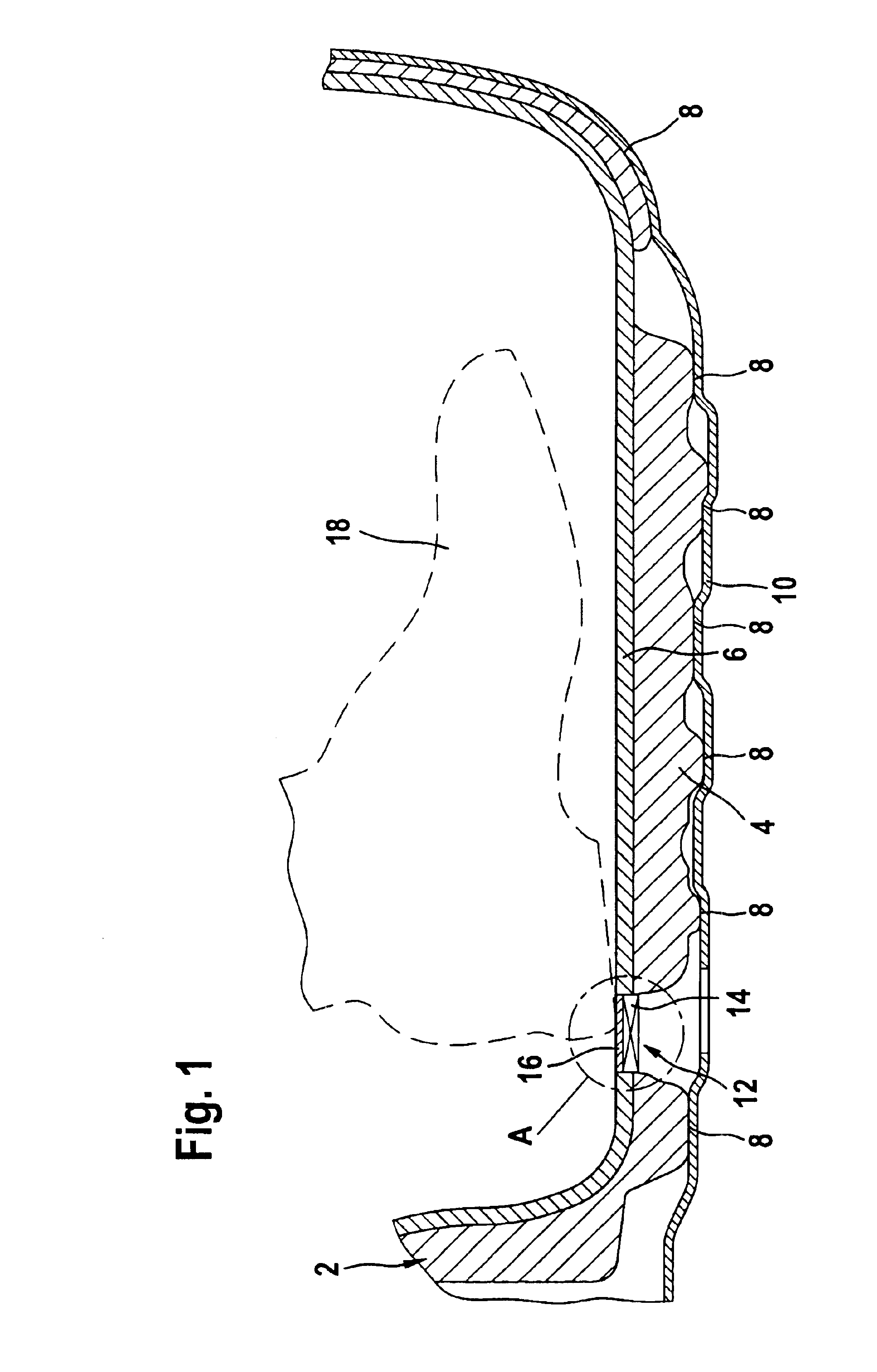
The floor covering furthermore comprises an affixing arrangement of 12 which comprises a first affixing element 14 which is releaseably connectable to a second affixing element of a (not illustrated) supplemental mat. The first affixing element 14 is attached to the base covering 2 and in the first embodiment is covered with a covering cap 16. The covering cap 16 is releaseably connected with the first affixing element 14 and covers this upwardly so that no soiling can intrude into the first affixing element 14.

Even though the covering cap 16 and the first affixing element 14 in FIG. 1 are only schematically illustrated, FIG. 1 clearly illustrates the advantages of a floor covering of the present invention in this first embodiment.

Because of the particular structure of the affixing arrangement 12, that is to say of the first affixing element 14, a higher driving comfort is provided since the affixing element 14 does not intrude into the movement area of the foot 18. An accidental co...

second embodiment

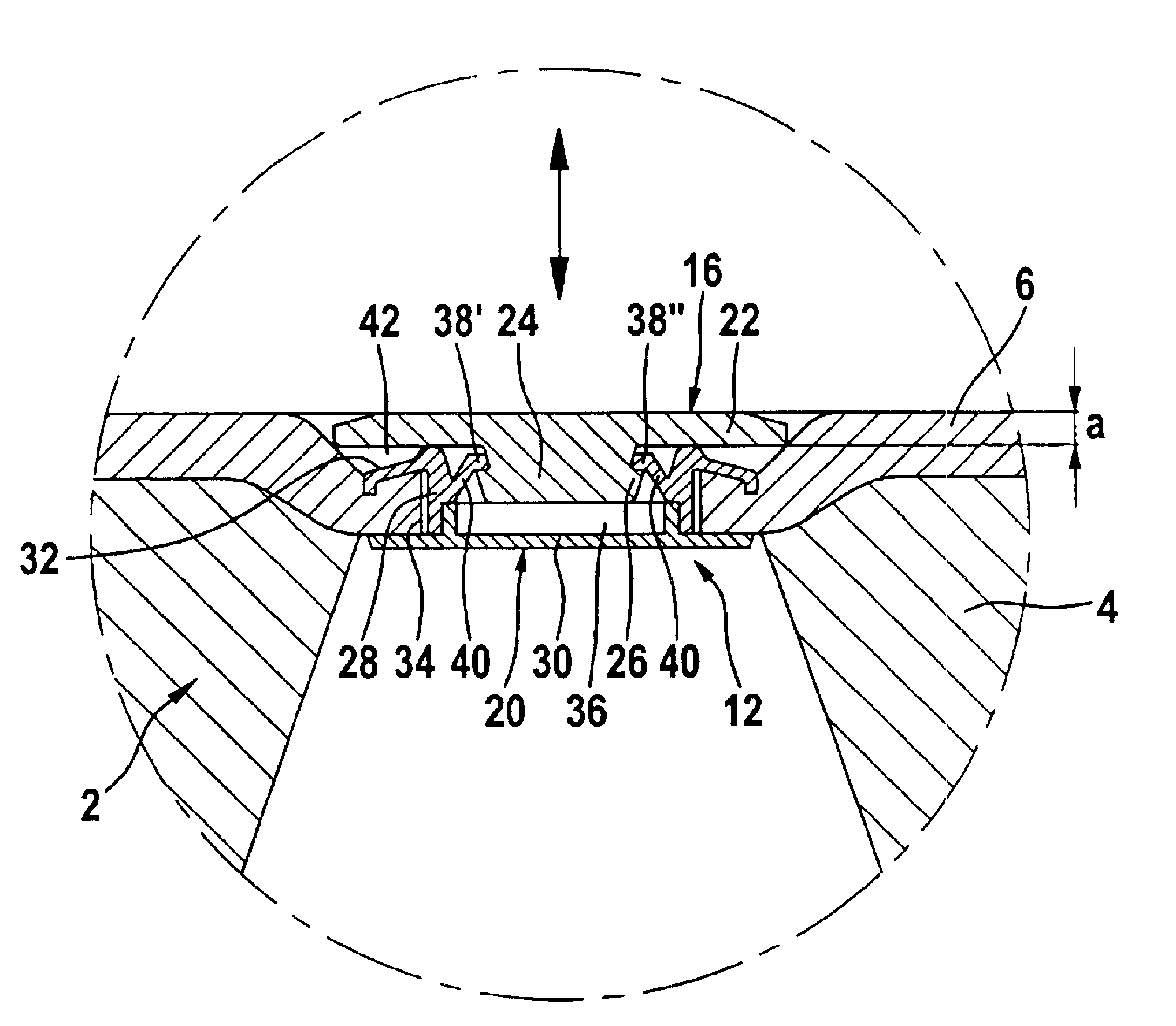
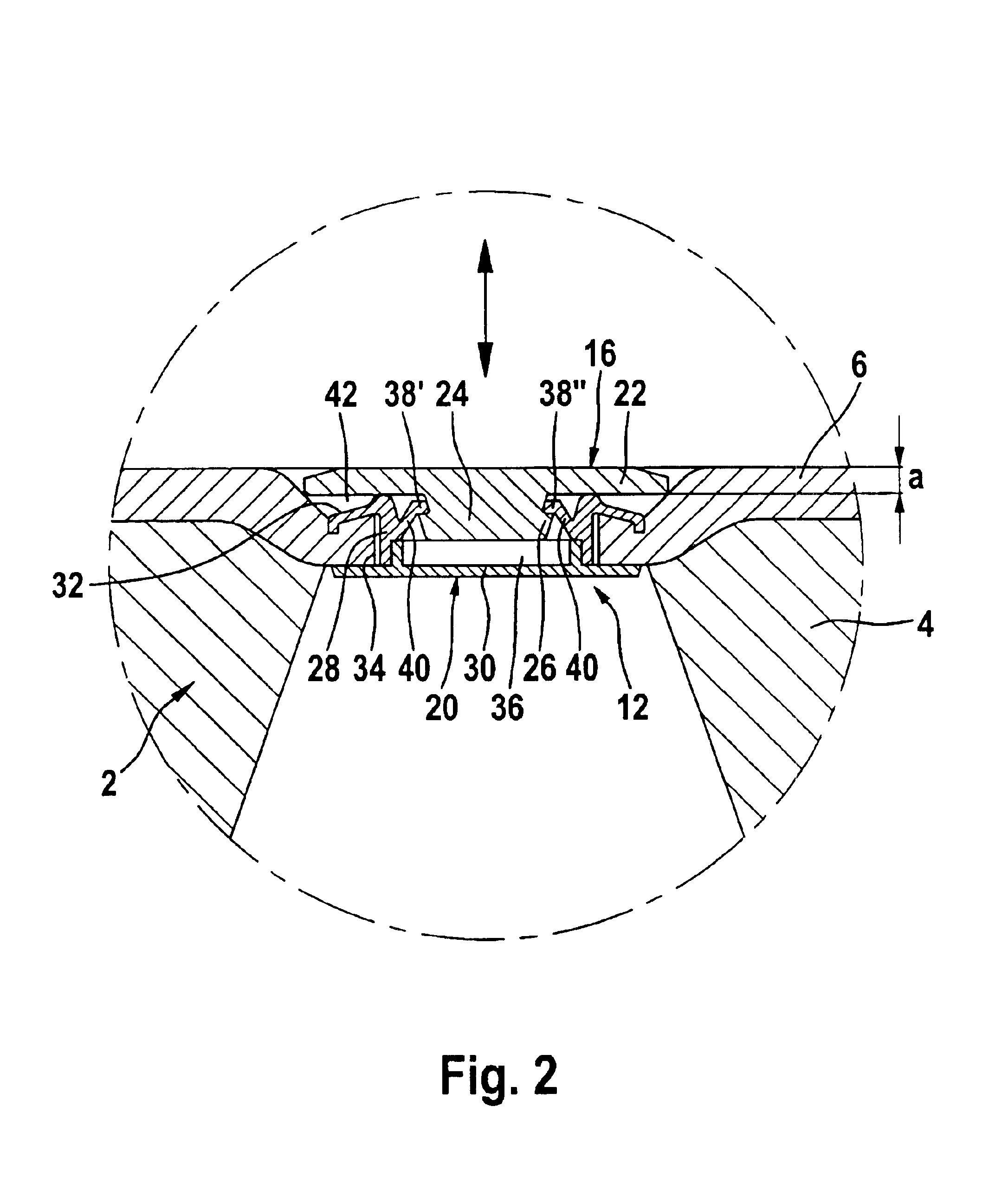
FIG. 3 illustrates the particular advantages of the floor covering of the Through the special construction of the affixing arrangement 56', 56" a higher driving comfort is provided which results from the absence of an upward doming of the supplemental mat 42 in the region of foot space above the affixing arrangement 56', 56". Furthermore, the supplemental mat 42 follows the contour of the base covering 44 and lies evenly upon base covering 44 so that the freedom of movement of foot 54 is in no way restricted. An accidental contact with the affixing arrangement 56', 56" and possible damage thereto, is impossible. The structure of the affixing arrangement 56', 56" is described herein below with respect to FIGS. 4 and 5.

FIG. 4 shows the affixing arrangement in a first embodiment 56'. The affixing arrangement 56' comprises a first affixing element 58 and a second affixing element 60. The second affixing element 60 comprises a circumferential plate 62 which is provided at the midpoint t...


PUM

PropertyMeasurementUnit
heightaaaaaaaaaa
force-aaaaaaaaaa
forceaaaaaaaaaa

Abstract

The present invention is directed to a floor covering for a powered vehicle having a base covering 44 and a least one affixing arrangement 56'' for the affixing of the supplemental mat 42 to the base covering wherein the affixing arrangement 56'' comprises a first affixing element 20 which may be connected releaseably with a complementary second affixing element 60 provided to the supplemental mat 42. In accordance with the present invention the first affixing element 20 is embedded in the base covering 44 wherein the upwardly extending distal end of the first affixing element 20 is provided no higher than the level of the nap side of the base covering 44. A further embodiment of the floor covering of the present invention comprises the supplemental mat 42 wherein a second affixing element 60 is invisibly provided to its underside. The driving comfort is also increased thereby, that the affixing arrangement 46 does not intrude into the foot space and a secure attachment of the supplemental mat 12 is obtained by the covering of the attaching arrangement 56.

Description

Floor covering for a powered vehicle having a base floor covering and at least one affixing arrangement for affixing a supplemental mat to the floor covering.DISCUSSION OF THE PRIOR ARTThe state of the art recognizes a differentiable floor covering for power vehicles, which comprises a floor covering which at least directly lies on the bodywork, a plurality of attaching arrangements and a plurality of supplemental mats, whereby the latter are attachable to the floor covering by means of attaching attachments.German patent DE19823230A1 discloses a floor covering for an automobile which comprises a carpet base and a floor mat attachable thereto. Upon the carpet base there is a provided a raised base plate with an upwardly protruding post which comprises an outwardly radialy extending head segment. The base plate is attached to the carpet base wherein links from the base plate extend thru a hole in the carpet base into which they grip. Similarly in the floor mat, a hole is provided, wh...

Claims


Application Information

Patent Timeline
Patent Type & Authority Patents(United States)
IPC IPC(8): B60N3/04
CPCB60N3/046Y10T16/118Y10T428/24Y10T16/10Y10T428/24008Y10T428/24025Y10T428/23979
Inventor GENSLER, MANFRED
Owner DURA TUFTING
Why Eureka
Try Eureka