Semiconductor processing temperature control

a technology of semiconductors and temperature control, applied in the field of semiconductor processing temperature control, can solve the problems of increasing the need for accurate temperature control, high floor space cost, and high building and operation costs, and achieves the effects of reducing valve switching, improving reliability, and low thermal shock

Inactive Publication Date: 2004-11-23
NOAH PRECISION INC
View PDF7 Cites 62 Cited by
  • Summary
  • Abstract
  • Description
  • Claims
  • Application Information

AI Technical Summary

Benefits of technology

Accordingly, the principles of the present invention are directed to a semiconductor process temperature control system that heats and cools a target using one temperature control fluid. Beneficially, the principles of the present invention are implemented using a re-circulation loop that is pressurized by one pump (or one pumping system). The principles of the present invention can be implemented with low thermal shock and reduced valve switching, and thus with improved reliability. Furthermore, the principles of the present invention can be implemented with relatively high efficiency.
A semiconductor process temperature control system according to the principles of the present invention includes a re-circulation loop for retaining and circulating a volume of temperature control fluid such that the temperature control fluid is in thermal communication with a target whose temperature is being controlled. The temperature control fluid is circulated through the re-circulation loop by a fluid pump. The re-circulation loop includes control valves that selectively enable some of the temperature control fluid to flow through a cooling heat exchanger, through a heating heat exchanger, or through neither heat exchanger. The control valves are controlled by a controller, which receives temperature information that is related to the temperature of the target from at least one temperature sensor. Based on the temperature information, some of the temperature control fluid is passed through a selected heat exchanger such that the target achieves a predetermined temperature. Beneficially the controller further receives time information from a timer. In such cases, the controller controls the flow of the temperature control fluid such that the temperature of the target follows a predetermined temperature profile. This enables continuous etching of a semiconductor wafer at different temperatures that change according to a well-defined temperature profile.
Beneficially, the re-circulation loop retains a volume of temperature control fluid such that the temperature control fluid can change temperatures relatively rapidly. Furthermore, the re-circulation loop beneficially passes only part of the temperature control fluid through a heat exchanger. This reduces thermal stress and stabilizes re-circulation loop pressures.

Problems solved by technology

While clean rooms are generally successful, they are expensive to build and operate, with the cost being highly dependent on floor space.
Increasing etching difficult is that as semiconductors get denser, the need for accurate temperature control becomes greater.
This increased the risk of wafer contamination, necessitated multiple etching vessels and temperature control systems, increased processing time, and increased the required clean room floor space.
Semiconductor wafer removal was required because it was very difficult or impossible to rapidly change a vessel's temperature, and because it was very difficult or impossible to control the temperature's rate of change.
While beneficial, prior art semiconductor process temperature controls usually either cooled or heated targets, but not both.
Such systems required multiple circulation pipes through the targets, which increased cost and reduced reliability.
Furthermore, temperature adjustment and regulation requires rapid valve switching and flushing of the temperature control fluid.
This can detrimentally impact reliability because of thermal stresses and pressure mismatches between the heating and cooling subsystems.
Furthermore, mass mixing between the heated and cooled temperature control fluids leads to increased power consumption because previously heated temperature control fluid must be cooled, while previously cooled temperature control fluid must be heated.

Method used


Image

  • Semiconductor processing temperature control
  • Semiconductor processing temperature control
  • Semiconductor processing temperature control

Examples


Embodiment Construction

Reference will now be made in detail to an illustrated embodiment of the invention, the example of which is shown in the accompanying drawings.

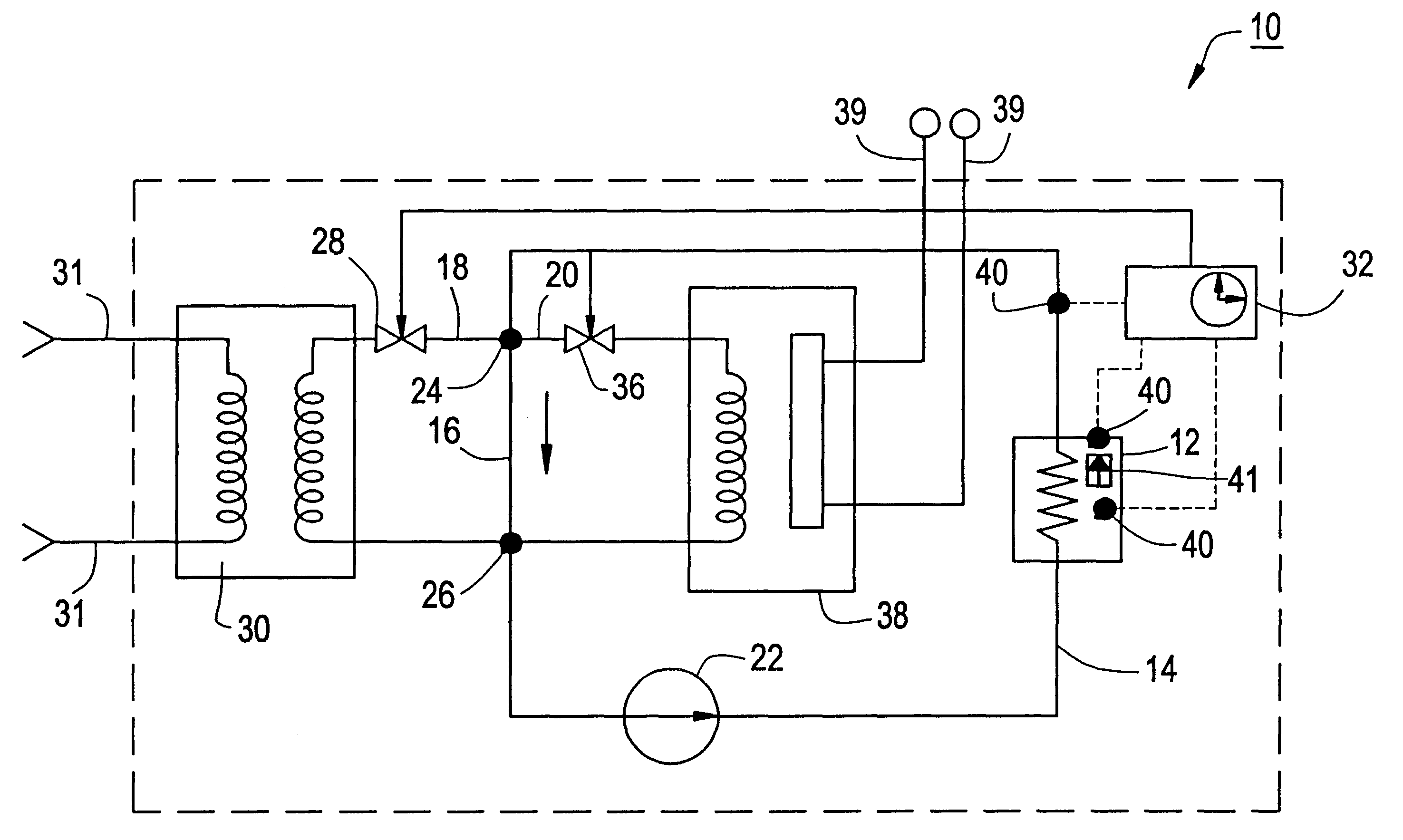
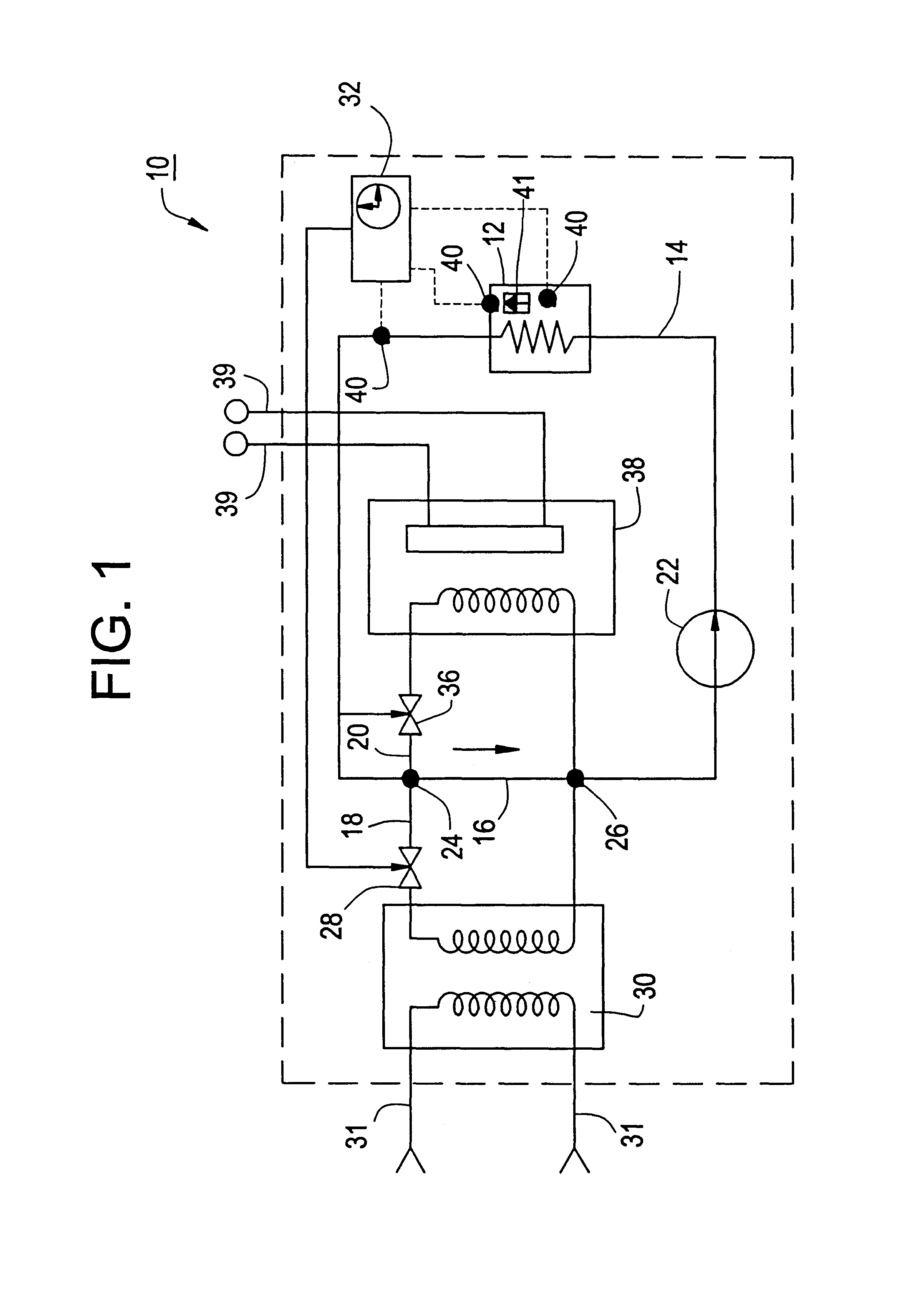
FIG. 1 illustrates a semiconductor process temperature control system 10 that is in accord with the principles of the present invention. The semiconductor process temperature control system 10 both heats and cools a target 12, as required, using a temperature control fluid in a re-circulation loop 14. The re-circulation loop 14 includes a through passage 16, a cooling passage 18, and a heating passage 20. The temperature control fluid is pumped through the re-circulation loop 14 by a pump 22.

Still referring to FIG. 1, the through passage 16, the cooling passage 18, and the heating passage 20 are in parallel. They meet at a first branch 24 and at a second branch 26. The through passage 16 transports some of the temperature control fluid directly from the first branch 24 to the second branch 26. The cooling passage 18 includes a cooling valve 2...


PUM


Abstract

A temperature control system having a re-circulation loop that uses valves to selectively circulate a temperature control fluid through a cooling system, through a heating system, or through a through passage so as to controlling the temperature of the temperature control fluid, which, in turn, controls the temperature of a target. A temperature sensor monitors the target's temperature. A controller controls valve operation in response to the temperature measured by the temperature sensor to obtain a predetermined target temperature. Beneficially, the controller controls the target's temperature according to a predetermined temperature profile. Continuous etching along a predetermined temperature profile is possible.

Description

1. Field of the InventionThe present invention relates to semiconductor processing temperature control. More specifically, it relates to controlling the temperature of a semiconductor processing device (target) using a temperature control fluid that is selectively heated and cooled. The temperature of the semiconductor processing device (target) is variable over time according to a predetermined temperature profile.2. Discussion of the Related ArtSemiconductor device manufacturing involves a large number of processing steps, such as semiconductor crystal growth, wafer cutting, wafer polishing, doping, material depositions, oxide growths, masking, and etching. Because modem semiconductors must be low cost and highly reliable, rapid fabrication with high device yields and with tight tolerances is critical. That generally requires automated equipment and processes in specially designed clean rooms.While clean rooms are generally successful, they are expensive to build and operate, with...

Claims


Application Information

Patent Timeline
Patent Type & Authority Patents(United States)
IPC IPC(8): H01L21/70H01L21/02H01L21/311H01L21/768H01L21/00F24F11/76
CPCG05D23/20H01L21/31111H01L21/76808H01L21/31133H01L21/67248
Inventor ATLAS, BORIS
Owner NOAH PRECISION INC
Why Eureka
Try Eureka