
Method and apparatus for extracting measurement information and setting specifications using three dimensional visualization

a technology of measurement information and three-dimensional visualization, applied in the direction of computer control, instruments, program control, etc., can solve the problems of incorrect estimation of objects, various problems in up and programming test/inspection machines, solder joints on printed circuit board assemblies,

Inactive Publication Date: 2004-11-30
AGILENT TECH INC
View PDF16 Cites 36 Cited by
  • Summary
  • Abstract
  • Description
  • Claims
  • Application Information

AI Technical Summary

Problems solved by technology

Such a system may detect defects in solder joints on printed circuit board assemblies (PCBA's) that are single sided or doubled sided.
Drawbacks of automated test equipment tend to be related to the set-up and the programming of the equipment.
In many instances the estimates do not correctly classify the objects.
This process of setting-up and programming a test / inspection machine has various problems.
Such problems include that it is tedious and slow.
This process is highly subjected to human error, human repeatability errors, and human fatigue errors.
This process further has the drawback of requiring the programmer to have a cognitive ability to relate physical parameters (e.g. related to shape) to numerical parameters.
This is very difficult when a human must visualize 10 or more parameters simultaneously.
Another drawback is that the programmer must translate the visual form (or deformity) to a parameteric value.
Furthermore, due to the programming process being tedious and difficult, many programmers "give up" before the system is well programmed or tuned.
Also, even if a system is well tuned, operators may believe that the limits are not set correctly and therefore allow out of spec parts to "pass" inspection.
Again, this is a long, tedious and prone to error programming process.
This process is timely, somewhat trial and error based, and manually intensive to perform.

Method used


Image

  • Method and apparatus for extracting measurement information and setting specifications using three dimensional visualization
  • Method and apparatus for extracting measurement information and setting specifications using three dimensional visualization
  • Method and apparatus for extracting measurement information and setting specifications using three dimensional visualization

Examples


Embodiment Construction

The present invention will now be described more fully hereinafter with reference to the accompanying drawings, in which preferred exemplary embodiments of the present invention are shown. This invention may, however, be embodied in many different forms and should not be construed as limited to the embodiments set forth herein; rather, these embodiments are provided so that this disclosure will be thorough and complete, and will convey pertinent aspects of the invention.

Unlike prior inspection systems, which burden a programmer to translate desired visual features of an object into physical quantifiable parameters, the exemplary embodiments of the present invention provide an apparatus and process that performs the translation from human terms into physical quantifiable parameters.

Referring now to FIG. 8, and by way of example, suppose a physical object 801 such as a piece of pipe is to be inspected and a programmer wanted to program an inspection machine by utilizing a sample piece...


PUM


Abstract

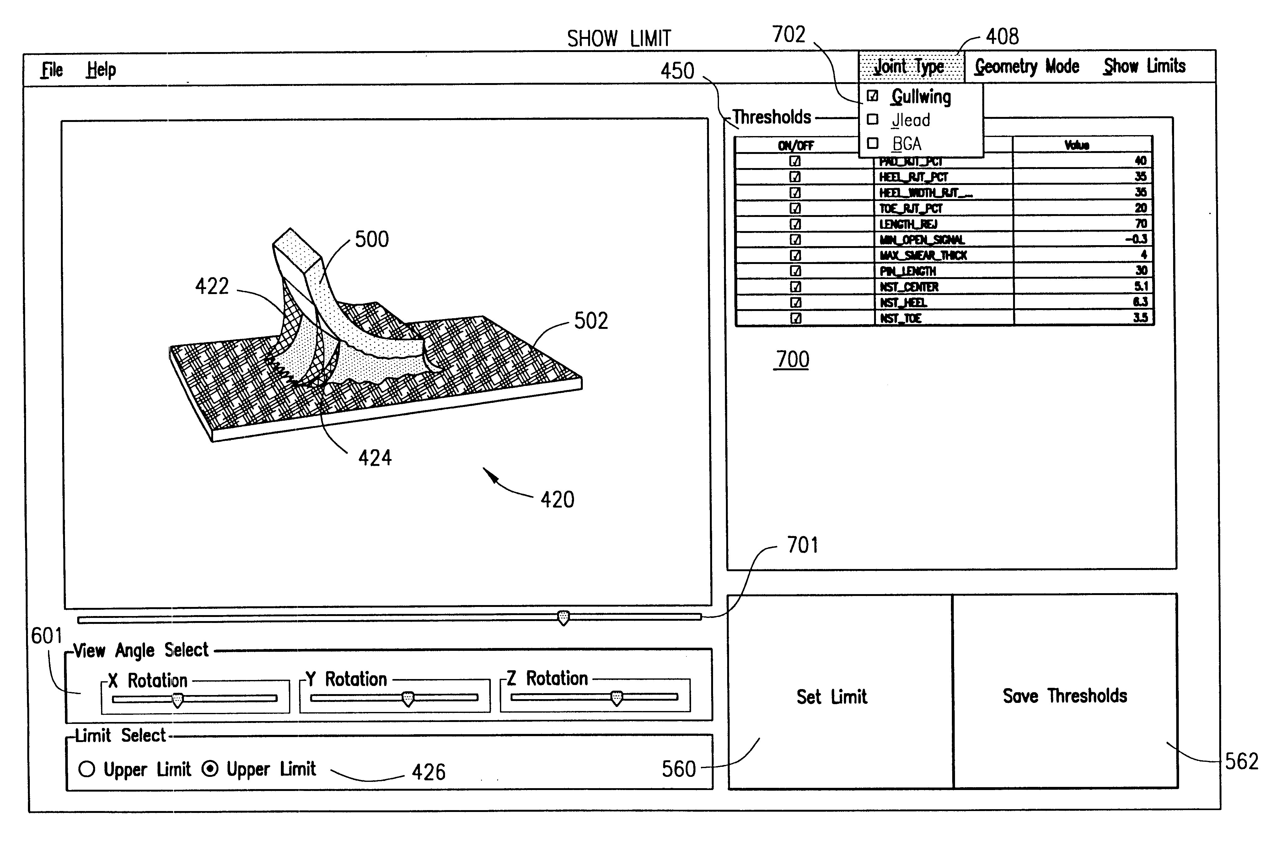
The present invention provides an apparatus and method for viewing a depiction of an object (for example a solder joint) in a multi-dimensional manner, morphing the object's depiction using a graphical user interface to upper and lower acceptable tolerance limits and storing the tolerance limits for use in a test / inspection apparatus. The invention relates to the translation of human visual inspection-analysis of an object into physical quantifiable parameters used in an inspection device via a graphical user interface.

Description

1. Field of the InventionThe present invention relates to the translation of human visual inspection analysis of an object into physical quantifiable parameters used in an inspection device via a graphical user interface. The present invention further relates to displaying a multidimensional depiction of a manufactured item or classifiable item and then morphing the three dimensional depiction to establish maximum and minimum ranges for various dimensions and aspects of the manufactured item. More particularly, the present invention relates to a method and apparatus for viewing a three dimensional depiction of a solder joint then morphing the depiction of the solder joint to establish maximum and minimum acceptable limits for such solder joint being viewed and tested in a classification / manufacturing test apparatus.2. Description of Related ArtOne goal of inspection processes is to classify a device which is under inspection into one of two (or many) categories based on some criteri...

Claims


Application Information

Patent Timeline
IPC IPC(8): G05B19/401
CPCG05B19/401G05B2219/37205G05B2219/37207Y10S715/964G05B2219/37569G05B2219/45135G05B2219/37567
Inventor FAZZIO, RONALD SHANEBUCK, DEAN C
Owner AGILENT TECH INC
Learn More