High frequency, blind mate, coaxial interconnect

a coaxial interconnection and high frequency technology, applied in the direction of coupling contact members, coupling device connections, electric discharge lamps, etc., can solve problems such as mechanical stress that may be encountered, and achieve the effect of maintaining the desired connection

Inactive Publication Date: 2004-12-07
CORNING OPTICAL COMM LLC
View PDF28 Cites 135 Cited by
  • Summary
  • Abstract
  • Description
  • Claims
  • Application Information

AI Technical Summary

Benefits of technology

Accordingly, an object of the present invention is to provide a coaxial transmission medium connector that securely and reliably maintains the desired connection.
Another object of aspects of this invention is to provide such a coaxial transmission medium connector and a coaxial transmission medium assembly in which the effects of mechanical stress at the connection point can be accommodated without unduly affecting the performance of the connection.
Each of the cantilevered beams preferably is coupled to the base portion at the transition portion and the transition portion comprises a non-orthogonal profile. The base portion preferably comprises an external surface, each of the cantilevered beams comprises an external surface, and the transition portion is positioned is positioned at the external surfaces of the base portion and each of the cantilevered beams. The non-orthogonal profile preferably comprises a curved profile, e.g., a radial profile. Such profiles may be useful in distributing stress in the outer conductor portion when the cantilevered beams are flexed radially inward. The tapering profile preferably is continuous and constant. It is preferred that the tapering profile spans at least 80 percent of the length of the cantilevered beams.

Problems solved by technology

A problem that has been found to be associated with junctions affected by such a connector system is the mechanical stress that may be encountered in the outer beams 40 and 41.

Method used


Image

  • High frequency, blind mate, coaxial interconnect
  • High frequency, blind mate, coaxial interconnect
  • High frequency, blind mate, coaxial interconnect

Examples


Embodiment Construction

Reference will now be made in detail to the presently preferred embodiments and methods of the invention as illustrated in the accompanying drawings, in which like reference characters designate like or corresponding parts throughout the drawings. It should be noted, however, that the invention in its broader aspects is not limited to the specific details, representative devices and methods, and illustrative examples shown and described in this section in connection with the preferred embodiments and methods. The invention according to its various aspects is particularly pointed out and distinctly claimed in the attached claims read in view of this specification, and appropriate equivalents.

It is to be noted that, as used in the specification and the appended claims, the singular forms "a," "an," and "the" may include plural referents unless the context clearly dictates otherwise.

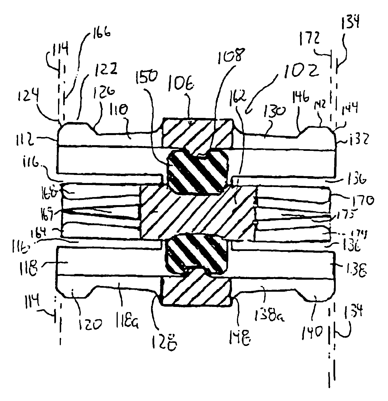
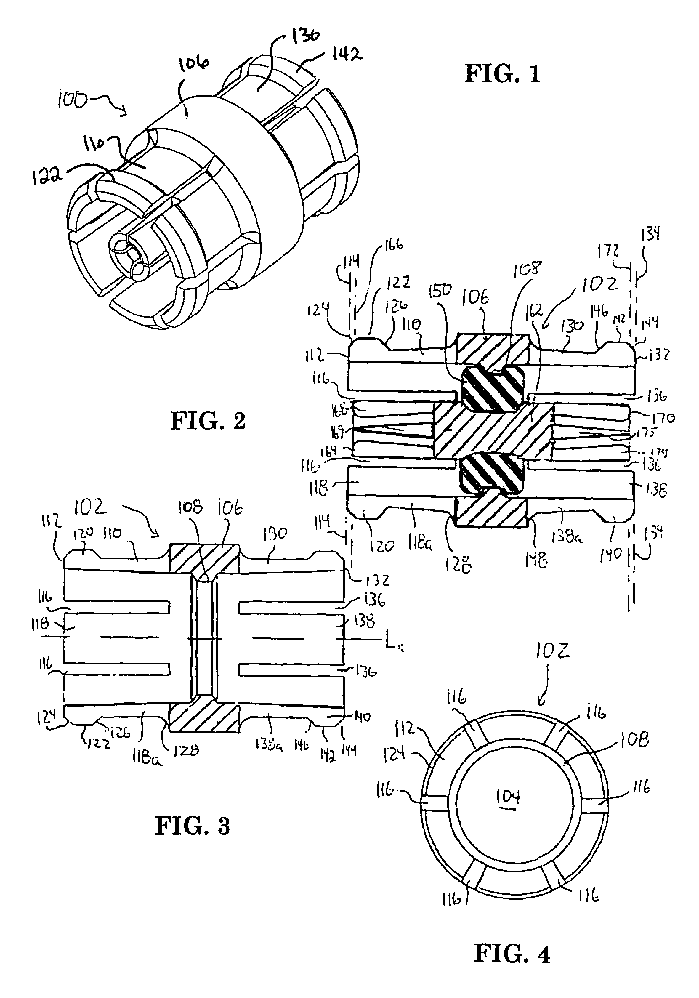
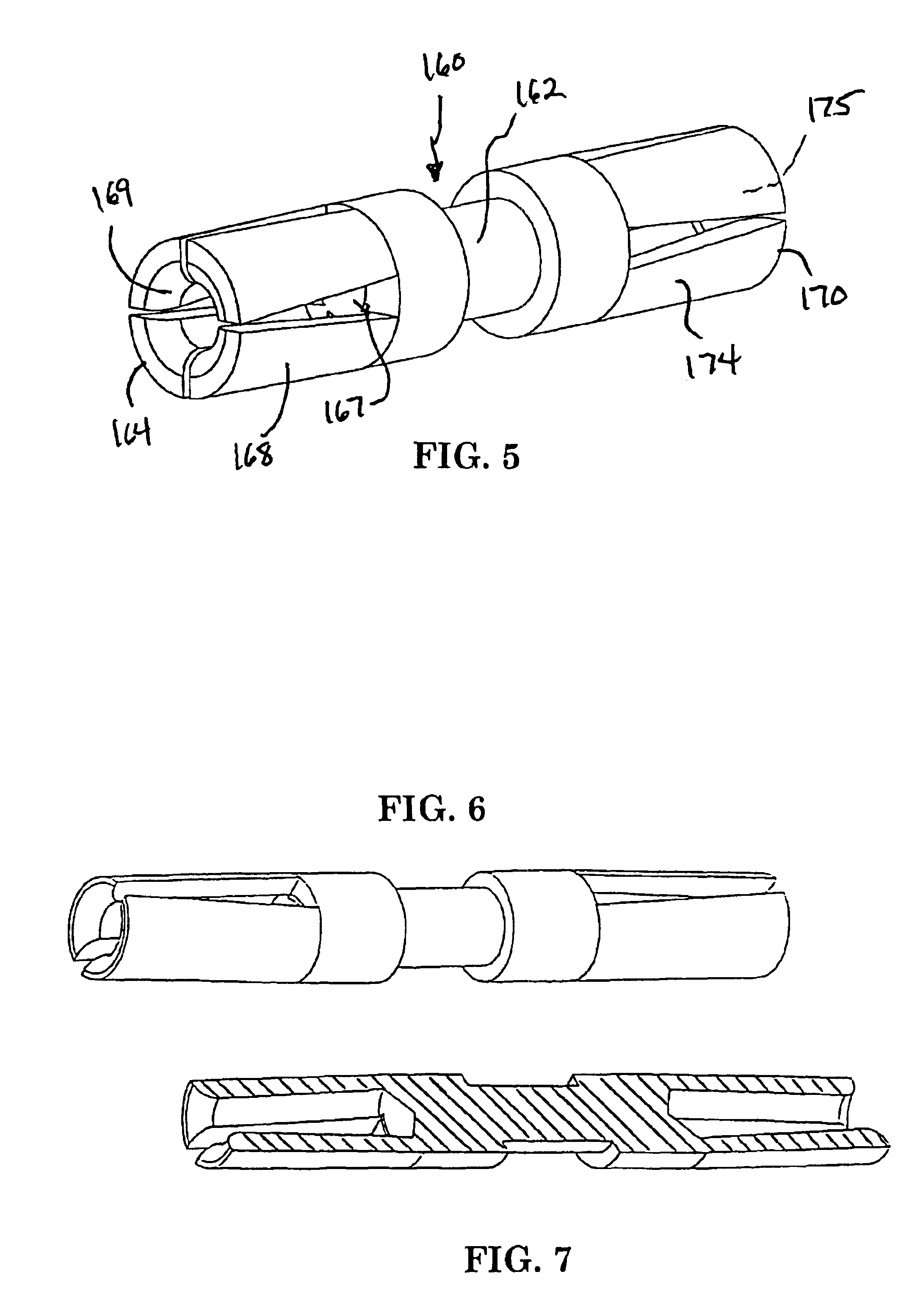
In accordance with one aspect of the invention, a coaxial transmission medium connector is provided for ...


PUM


Abstract

A coaxial transmission medium connector is provided which includes an outer conductor portion for electrically coupling to the outer conductor of a coaxial transmission medium. The outer conductor portion includes a base portion, a plurality of cantilevered beams, and a plurality of slots extending about a longitudinal axis. Each of the cantilevered beams is coupled to the base portion at a transition portion and terminates at a distal end. A center conductor portion is disposed within the central bore of the outer conductor portion for electrically coupling to the inner conductor of the coaxial transmission medium. Related apparatus and methods are provided.

Description

1. Field of the InventionThe invention relates generally to electrical connectors for coupling together coaxial transmission media, such as coaxial cables, modules, ports, combinations thereof, and the like. The invention is well suited for application to connectors for connecting coaxial transmission media operating or operable in the microwave frequency range and similar frequency regimes.2. Description of the Related ArtCoaxial transmission media for conveying information at microwave frequencies are often particularly characterized by their relatively small size which is not only a consequence of the operation frequency range, but is also particularly attributable to the applications and environments of the systems in which they are employed. Such systems, for example, may be found in sophisticated aircraft in which the size and weight of microwave electronics systems often must be small and light as possible, yet durable and reliable.An example of a known coaxial transmission m...

Claims


Application Information

Patent Timeline
Patent Type & Authority Patents(United States)
IPC IPC(8): H01R13/115H01R13/00H01R13/646H01R24/38H01R43/00
CPCH01R13/6315H01R24/40H01R2103/00H01R24/542H01R9/05
Inventor HALL, RICHARD D.ELLIS, DAVID M.
Owner CORNING OPTICAL COMM LLC
Why Eureka
Try Eureka