

Method, system, and program for implementing a database trigger
a database and trigger technology, applied in the field of method, system and program for implementing a database trigger, can solve the problem that the transition variable cannot be stored in the same work fil
- Summary
- Abstract
- Description
- Claims
- Application Information
AI Technical Summary
Benefits of technology
Problems solved by technology
Method used
Image

Examples
Embodiment Construction
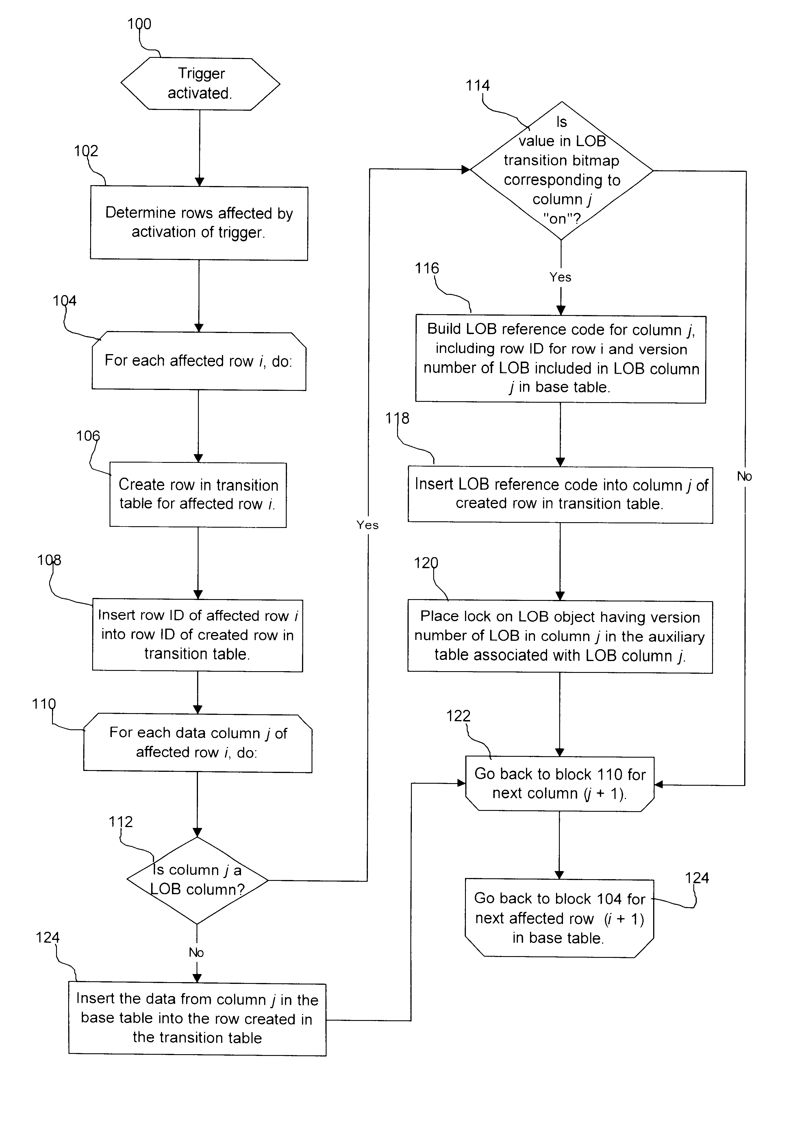
Provided is a method, system, and program for implementing a database trigger. Upon detecting a trigger event, a determination is made of at least one row in a base table affected by the trigger event. For each column in the base table of a data type that is referenced in a triggered action associated with the trigger event, a reference is generated referencing the data of the data type. The reference is inserted in a transition table column including data of the data type from the affected row in the base table referenced in the triggered action. The reference is used to access the data of the data type when performing the triggered action.
In further implementations, the reference includes a row identifier and version number of the data in the base table column referenced by the triggered action.
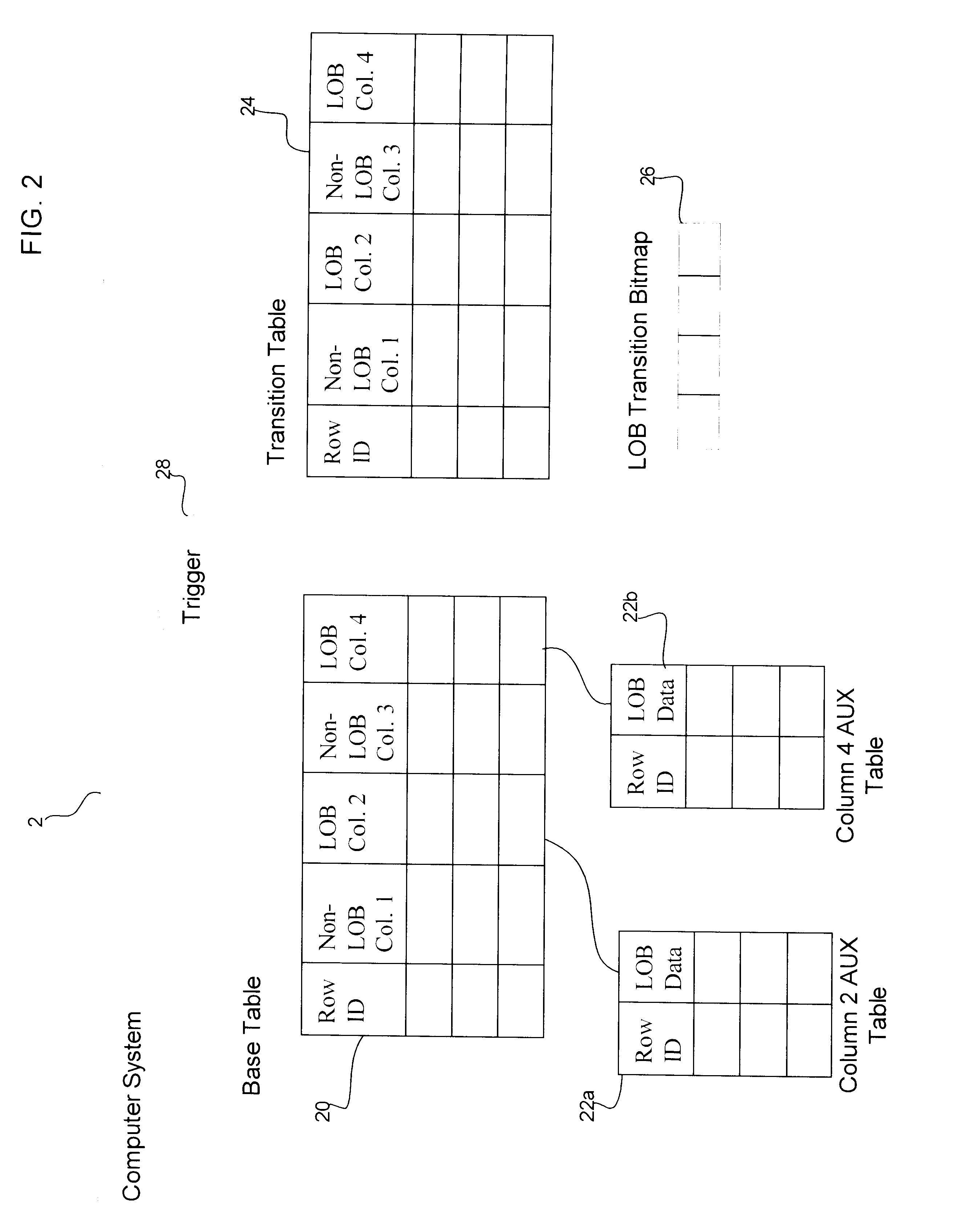
Still further, the data type for which the reference is generated comprises a large object data type. In such case, the reference is used to access the large object data by accessing an aux...
PUM
 Abstract
Description
Claims
Application Information