
Fluid dispenser

a dispenser and liquid technology, applied in the field of liquid dispensers, can solve the problem of not being able to use the refill or assembly without the pusher

Inactive Publication Date: 2004-12-21
VALOIS SA
View PDF6 Cites 14 Cited by
  • Summary
  • Abstract
  • Description
  • Claims
  • Application Information

AI Technical Summary

Benefits of technology

"The present invention is about a fluid dispenser that has a trim shell which holds the refill and dispensing member in a removable manner. The pusher is held captive by the trim shell and cannot be used without it. This prevents the refill or assembly from being used without the pusher. The pusher is essential for operating the dispenser, so it is not possible to use the refill or assembly without the pusher. The trim shell has a passageway in which the pusher is held captive and can move only far enough to actuate the dispensing member. The dispensing member has a closed bottom end and an open top end through which the assembly can be inserted. The actuating rod is connected to the pusher and is protected by the body of the dispensing member to prevent any conventional pusher from being fitted. This makes the dispenser safer and prevents untimely actuating of the dispensing member."

Problems solved by technology

Since the pusher is an element that is essential for operating the dispenser, it is not possible to use the refill or assembly without the pusher.

Method used


Image

  • Fluid dispenser
  • Fluid dispenser
  • Fluid dispenser

Examples


Embodiment Construction

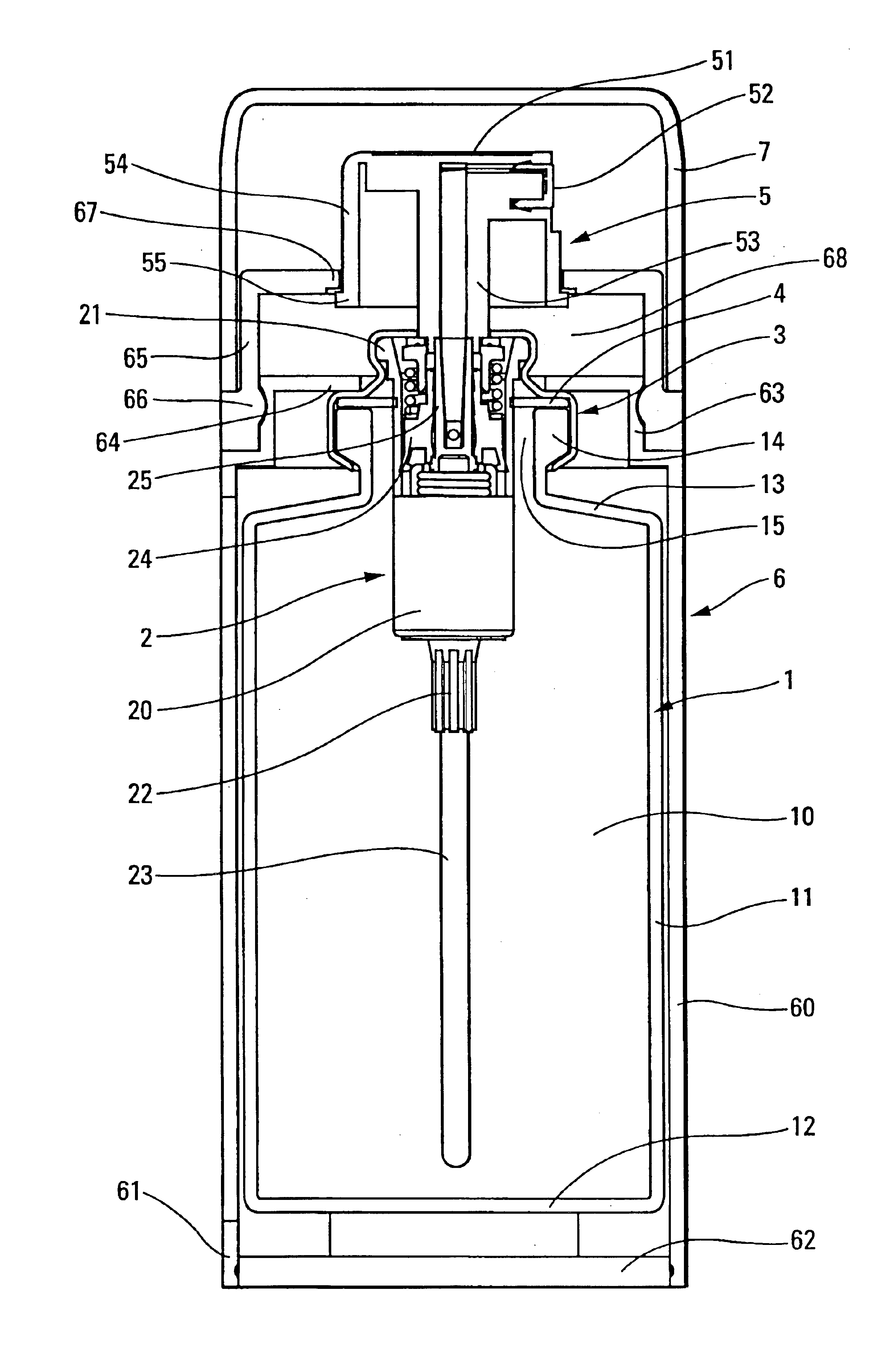
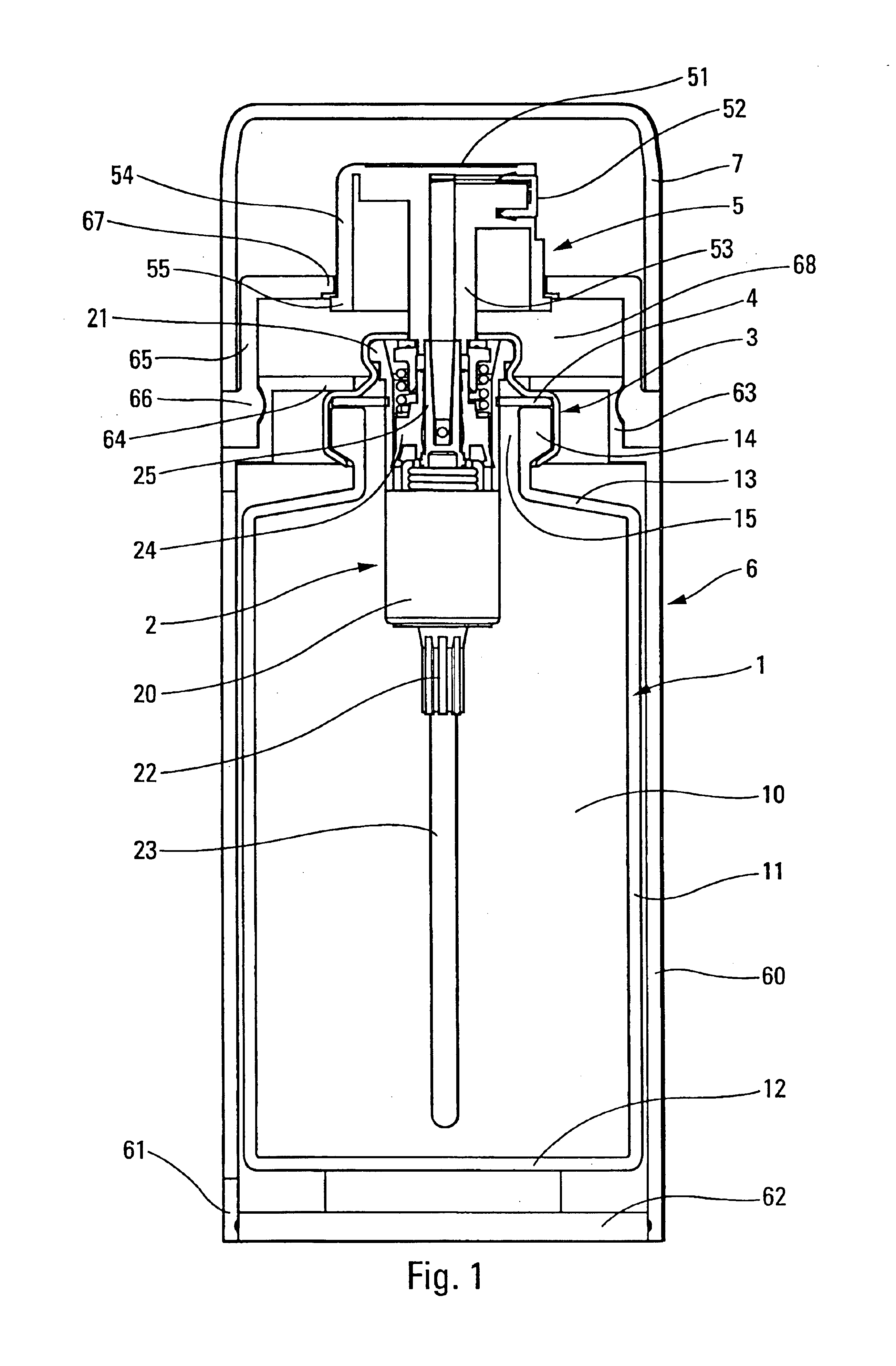
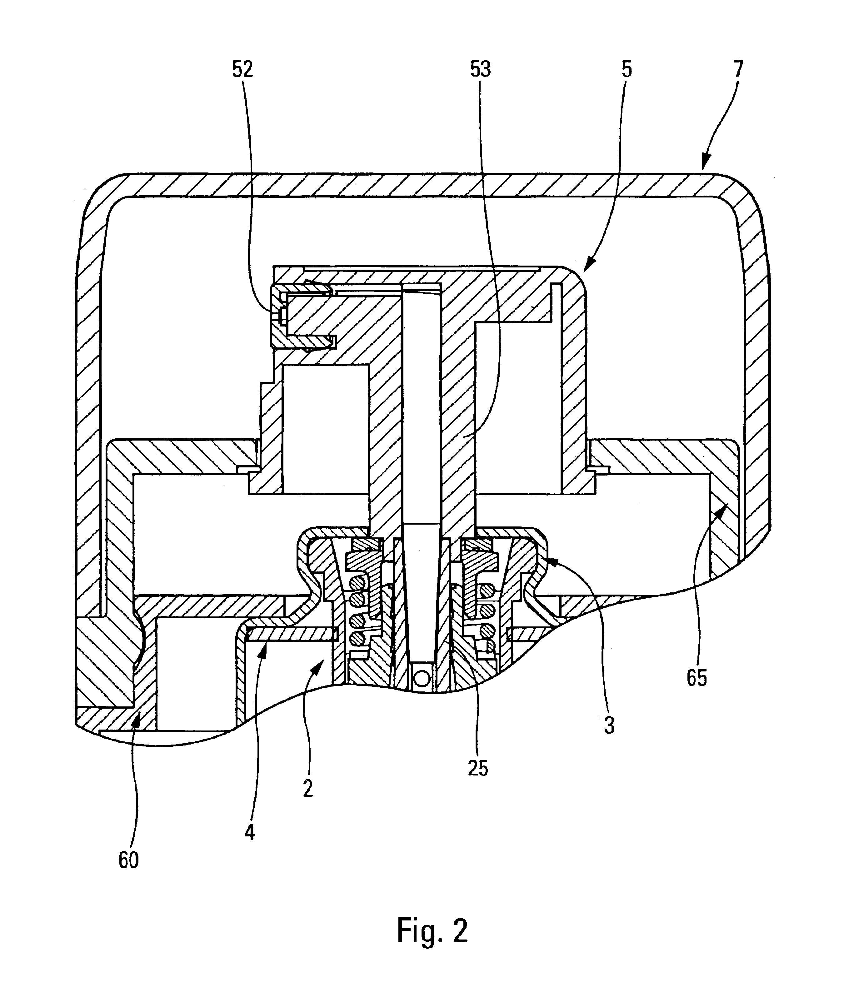
The fluid dispenser of the invention essentially comprises four component elements, namely a receptacle 1, a dispensing member 2, a pusher 5 and a trim shell 6. The dispenser further comprises a crimping ring 3 and a neck gasket 4, but these elements may be considered as being secondary. The dispenser may also optionally further comprise a cap 7 fitted to the trim shell 6.

The receptacle 1 may be a conventional receptacle, e.g. in the form of a bottle defining a reservoir 10 serving to contain fluid, e.g. a perfume. The receptacle 1 comprises a drum 11 which may be cylindrical or optionally convex. The drum 11 is terminated at its bottom end by a bottom 12, and, at its top end, it is provided with a shoulder 13 which is terminated by a neck 14 defining an opening 15. This is an entirely conventional form of fluid dispenser receptacle.

The dispensing member 2 may be a pump or a valve. In the example shown in FIG. 1, it is a pump comprising a body 20 whose bottom end is provided with a ...


PUM


Abstract

A fluid dispenser, including: a receptacle defining a fluid reservoir and an opening; a dispensing member fitted in the opening of the receptacle, and provided with an actuating rod, and a pusher serving to be fitted to the actuating rod of the dispensing member. A trim shell is provided in which an assembly made up of the receptacle and of its dispensing member is adapted to be held in removable manner, and in that the pusher is held captive by the trim shell so that the actuating rod can be connected to the pusher only when inside the trim shell.

Description

The present invention relates to a fluid dispenser including a receptacle defining a fluid reservoir and an opening. A dispensing member such as a pump or a valve is fitted in the opening of the receptacle, and is provided with an actuating rod. A pusher is fitted onto the actuating rod of the dispensing member so that, by pressing on the pusher, the dispensing member is actuated and a metered quantity or "dose" of fluid is dispensed. This is an entirely conventional design for a dispensing member such as a pump or a valve used, for example, in the fields of perfumes, cosmetics, or indeed pharmaceuticals.In certain cases, the assembly made up of the receptacle, of the dispensing member, and of the pusher is received in a trim shell which may be in the form of a sheath whose appearance is pleasing. The assembly thus defined constitutes a sort of replaceable refill while the trim shell of pleasing appearance is kept to receive the new assemblies. That type of dispenser is used in part...

Claims


Application Information

Patent Timeline
Patent Type & Authority Patents(United States)
IPC IPC(8): B05B11/00B65D83/16B65D83/14B65D47/34
CPCB05B11/0037B65D83/384B65D83/205B05B11/3025B05B11/0038B05B11/1025
Inventor GARCIA, FIRMIN
Owner VALOIS SA
Learn More