
Image processing system and method, and image display system

a technology of image processing and display system, applied in the direction of television system, signal generator with optical-mechanical scanning, instruments, etc., can solve problems such as picture jumping phenomenon, discontinuous display phenomenon, and blue phenomenon

Inactive Publication Date: 2004-12-28
JAPAN DISPLAY CENTRAL CO LTD
View PDF10 Cites 73 Cited by
  • Summary
  • Abstract
  • Description
  • Claims
  • Application Information

AI Technical Summary

Benefits of technology

"The present invention relates to an image processing system and method for improving the quality of moving pictures displayed on various devices. The technical effect of this invention is to reduce blurring and discontinuous display phenomena during the display of moving pictures, which can be caused by the speed of the moving object and the refresh rate of the display device. The invention incorporates input frame pictures based on an input picture signal and an input synchronizing signal, records the incorporated frame pictures in a memory, and produces output frame pictures by interpolating or thinning out the input frame pictures. The method can also discriminate whether the picture to be displayed is a moving picture or a still picture."

Problems solved by technology

The hold type display device has a problem in that the blurred phenomenon and the discontinuous display phenomenon are caused during the display of a moving picture.
On the other hand, the impulse type display device has a problem in that the picture jumping phenomenon is caused during the display of a moving picture.
If the speed of the moving object increases with respect to the frame frequency, although a correct image is projected on retinas in time series, the image between the last frame and the next frame disappears as shown in FIG. 18, so that the interpolation processing is not sufficiently carried out in brains.
Thus, in conventional image display devices, there is a problem in that the picture quality deteriorates in accordance with the displayed contents.

Method used


Image

  • Image processing system and method, and image display system
  • Image processing system and method, and image display system
  • Image processing system and method, and image display system

Examples


first embodiment

(First Embodiment)

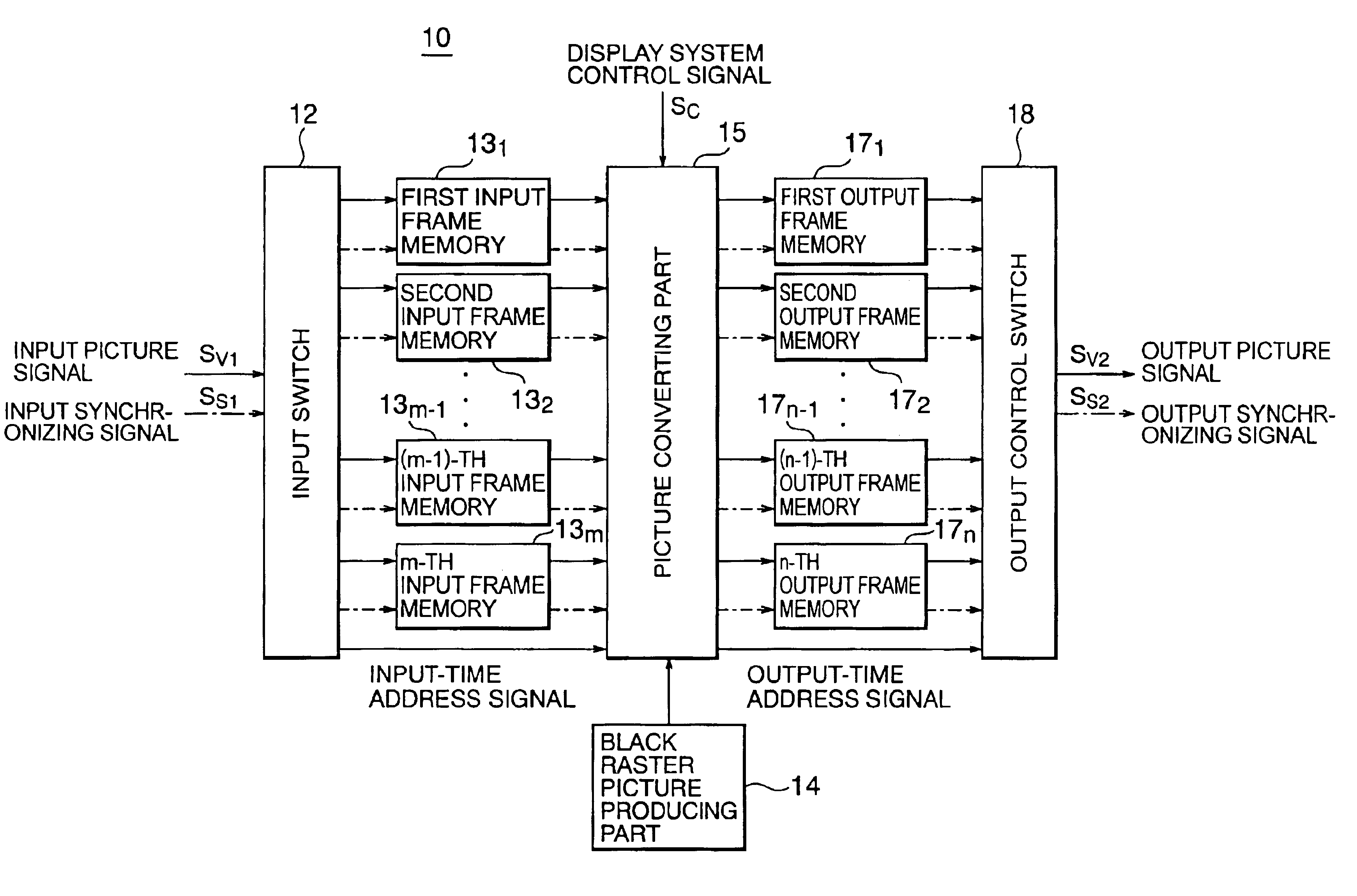
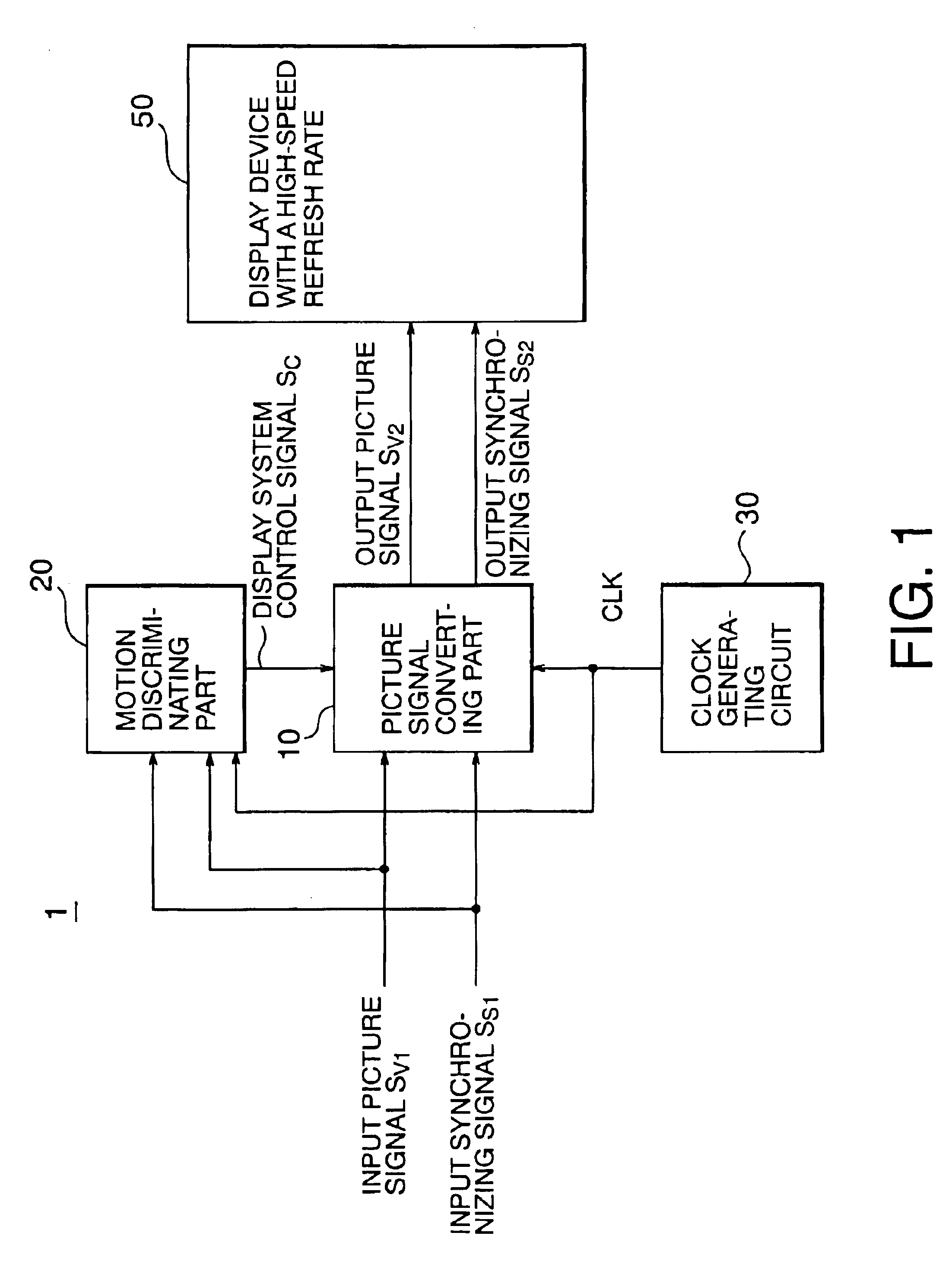
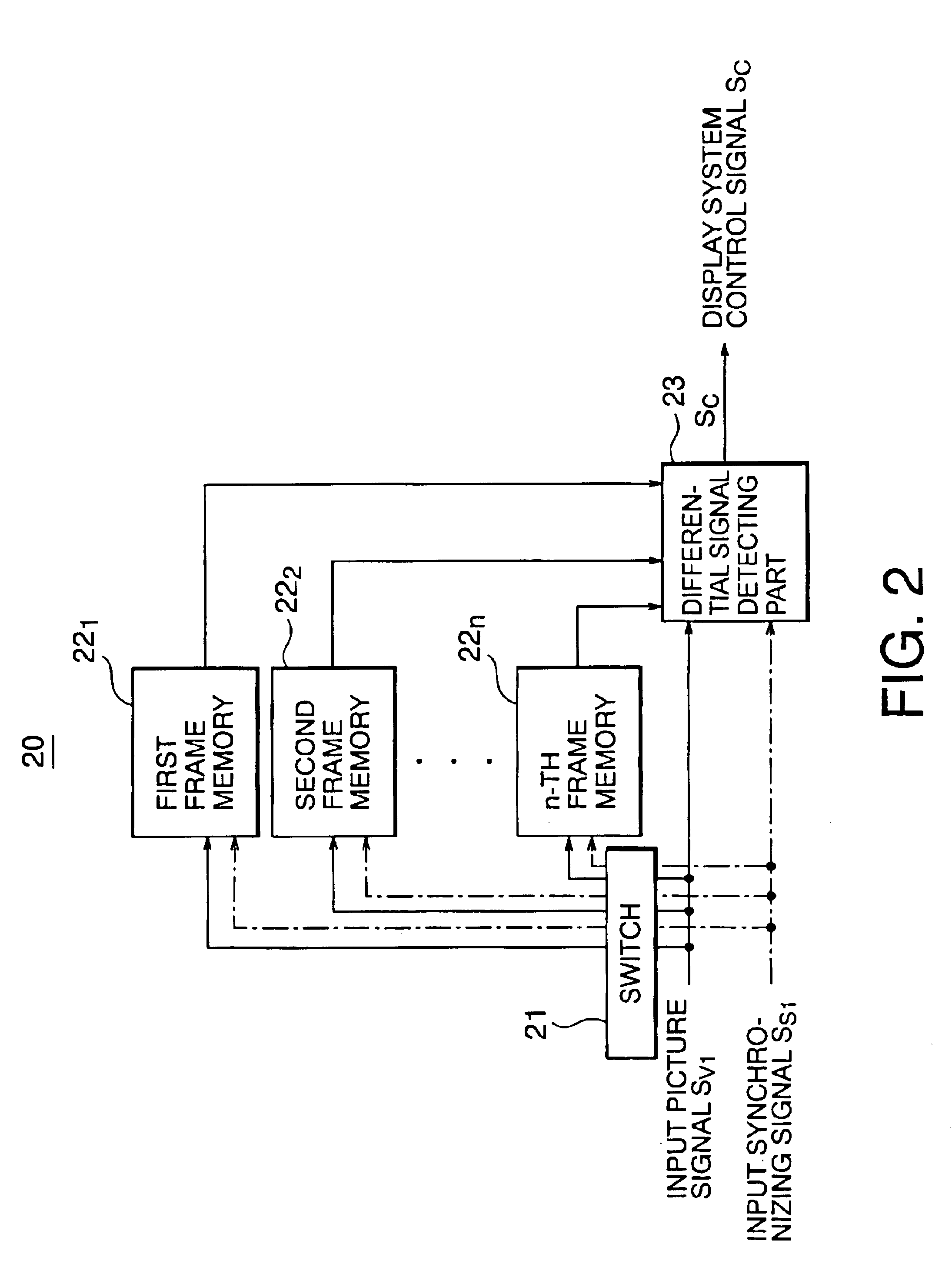
Referring to FIGS. 1 through 7, the first embodiment of the present invention will be described below. FIG. 1 shows the construction of the first embodiment of an image display system according to the present invention. In this embodiment, the image display system comprises an image processing device 1 and a display device with a high-speed refresh rate 50. The image processing device 1 comprises a picture signal converting part 10, a motion discriminating part 20 and a clock generating circuit 30.

The picture signal converting part 10 is designed to convert an input picture signal S.sub.v1 and an input synchronizing signal S.sub.S1, which are fed from the side of an image source (e.g., a personal computer, a digital versatile disk (DVD), an NTSC signal source or an HDTV signal source) on the basis of a display system control signal from the motion discriminating part 20 and a clock signal from the clock generating circuit 30, into an output picture signal S.sub.v2 ...

second embodiment

(Second Embodiment)

Referring to FIGS. 9 and 10, the second embodiment of the present invention will be described below. FIG. 9 shows the construction of the second embodiment of an image display system according to the present invention. The image display system 1A in the second embodiment is the same as the image display system 1 in the first embodiment, except that a moving / still picture indicating part 40 is further provided. The moving / still picture indicating part 40 is designed to transmit a moving / still picture indicating signal, which indicates whether the kind of a display picture displayed on the display device 50 is a moving picture or a still picture, to the picture signal converting part 10.

The moving / still picture indicating part 40 takes a system for determining a picture signal by an input synchronizing signal (e.g., determination of NTSC (National Television System Committee) system or PAL (Phase Alternation by Line) system, HDTV (High Definition Television) system)...

third embodiment

(Third Embodiment)

Referring to FIG. 11, the third embodiment of an image display system according to the present invention will be described below. In the third embodiment, the image display system is the same as the image display system in the first or second embodiment, except that the display device with a high-speed refresh rate 50 comprises a CRT having a fluorescent substance or an impulse type display device such as FED.

This embodiment is characterized in that when output pictures shown in FIGS. 8(c), 8(d) and 10(c) are displayed, the output of an output picture signal S.sub.v2 and an output synchronizing signal is stopped to provide a non-emission period in place of the output of a black raster picture. In the display device using a fluorescent substance, the relationship between the afterglow time of the fluorescent substance and a frame period should be noted. As shown in FIG. 11(b), a first fluorescent substance having a shorter afterglow time than the frame period is use...


PUM


Abstract

There is provided an image processing method capable of improving the picture quality. The image processing method comprises: incorporating input frame pictures to be displayed on a display device, on the basis of an input picture signal and an input synchronizing signal which is synchronized with the input picture signal; recording the incorporated input frame pictures in an input frame memory; and producing output frame pictures from input frame pictures, which have been recorded in the input frame memory, by producing an interpolated picture or inserting a black raster picture or thinning out the frame pictures, between input frame pictures corresponding to a picture information of the input frame picture to be displayed, on the basis of the picture information and the input synchronizing signal and an output synchronizing signal.

Description

This application is based upon and claims benefit of priority from the prior Japanese Patent Application No. 2000-189479, filed on Jun. 23, 2000; the contents of which are incorporated herein by reference.1. Field of The InventionThe present invention relates generally to an image processing system and method, and an image display system.2. Description of Related ArtAs conventional image display devices, there are two types of impulse type display devices (e.g., CRTs, field emission type display devices (which will be hereinafter referred to FEDs)), which continue to emit light only for the afterglow time of a fluorescent substance after writing an image, and hold type display devices (e.g., liquid crystal displays (which will be hereinafter referred to as LCDs), electroluminescent displays (which will be hereinafter referred to as ELDs)), which continue to hold the display of the last frame until a new image is written. There are also plasma display panels (which will be hereinafte...

Claims


Application Information

Patent Timeline
Patent Type & Authority Patents(United States)
IPC IPC(8): G09G5/00H04N7/01G09G3/36G09G3/30G09G1/16G09G3/22G06T1/00G03B21/00G09G3/20G09G5/36G09G5/391H04N5/66
CPCG09G3/20G09G5/005H04N7/01G09G5/006G09G1/167G09G3/22G09G3/30G09G3/3651H04N7/0137G09G2320/0257G09G2320/0261G09G2320/103G09G2340/0435H04N7/0132
Inventor ITOH, GOHOKUMURA, HARUHIKO
Owner JAPAN DISPLAY CENTRAL CO LTD
Learn More